© 2023 Carrier 16
INSTALLING THE YP PROGRAMMER MODULE
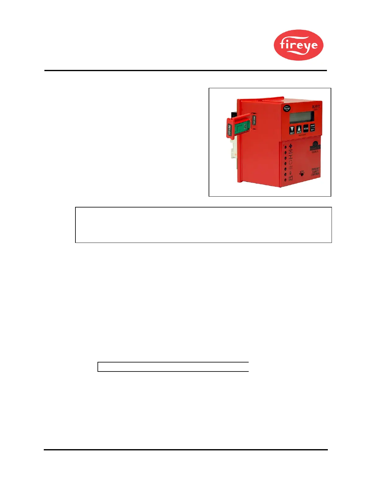
Figure 3. YP110 PROGRAMMER
The YP programmer module plugs into the side of
the YB110 (YB230) chassis module. They can
only be installed in one direction. DO NOT
ATTEMPT TO FORCE THE YP
PROGRAMMER INTO THE CHASSIS.
Referring to the illustration on the right, align the
holes in the YP programmer housing with the
posts located within the YB chassis. Push the YP
module into the chassis until the YP module is
flush with the YB housing. If it is necessary to
remove the YP programmer module from the YB
chassis, 2 slots are provided on the top and bottom
of the YP housing. A small screwdriver can be
used to ‘pop’ the programmer from the chassis.
NOTICE: For installations requiring CE certification:
After installation, the equipment should be protected from general access by means of a cabinet which is
only accessible with a key or special tool and therefore a clear responsibility who replaced the fuse. If the
fuse is blown during installation or operation, the control must be sent to the manufacturer to check.
ELECTRICAL CHECKOUT
If either a ground or a short circuit is detected, it must be eliminated before the control is
plugged into the wiring base and power turned on.
Test the electrical field wiring for short circuits and grounds. The recommended method
requires the use of an ohmmeter set on its lowest resistance scale.
7. Touch the meter probes together and calibrate accurately to ensure a reliable test.
8. Disconnect the neutral wire (L2) from the control system at the power source. Clip one
meter test lead to the grounded green wire or to terminal E and with the other probe
touch each other terminal. At no time should the meters show continuity or read 0 ohms.
9. Reconnect the neutral wire (L2) at the power source. Remove the test probe from the
grounded terminal and reconnect it to Terminal L2 in the wiring base. With the other
probe, touch each other terminal. It is normal to obtain a resistance reading on the meter
at some terminals during this test as there are resistive loads (coils, transformers, lamps,
etc.) connected whose normal DC resistance may be less than 5 ohms. The test meter
should not read zero ohms.
NOTICE: Restore power for the following test.
10. With your BurnerLogix installed, measure the voltage from L2 to all other terminals. The reading
must be zero on all terminals except Ll.
INSTALL BURNERLOGIX INTO WIRING BASE
The BurnerLogix YB chassis/amplifier module contains 2 screws permanently retained into the top and
bottom of the housing. The wiring base contains two brass inserts with recessed threads to ease the
installation. Line up the printed circuit board spacer located in the YB chassis/amplifier module with
the alignment tabs located in the wiring base. Firmly push the YB model into the wiring base to assure
the connectors mate properly. Tighten the screws into the brass inserts until snug.
 Loading...