–5 –
Section 23. SYSTEM OPERATION ................................................................................................... 79
Security Codes.................................................................................................................... 79
Keypad Functions .............................................................................................................. 80
Trouble Conditions ............................................................................................................ 82
Section 24. TESTING THE SYSTEM................................................................................................ 83
Test Procedure ................................................................................................................... 83
To the Installer .................................................................................................................. 84
Section 25. TROUBLESHOOTING GUIDE ................................ ................................ ..................... 85
Contacting Technical Support In The Event Of Problems .............................................. 87
REGULATORY AGENCY STATEMENTS ...................................................................... 88
Section 26. SPECIFICATIONS & ACCESSORIES ........................................................................ 89
Specifications ..................................................................................................................... 89
Accessories (Compatible Devices) ..................................................................................... 91
APPENDIX A. 5800 RF System Wireless Transmitters, Input Loop Identification Diagrams ....... 92
Index ................................ ................................ ................................ ........................................................ 94
Limitations Of This Alarm System.................................................................................................... 98
Summary Of Connections ................................................................................................................... 99
Limited Warranty................................................................................................................................ 100
Programming Form ................................................................................................ ........................ Insert
LIST OF FIGURES
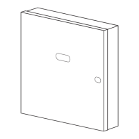
Figure 1.ÊÊInstalling the Cabinet Lock ................................ ................................ 10
Figure 2.ÊÊMounting The PC Board ................................ ................................ ..... 11
Figure 3.ÊÊMounting the PC Board & RF Receiver Together in the Cabinet..... 11
Figure 4.ÊÊTelephone Line Connections ............................................................... 12
Figure 5.ÊÊConnection of 4300 Transformer to the Control Board ..................... 13
Figure 6.ÊÊKeypad Connections to the Control Board ......................................... 15
Figure 7.ÊÊUsing a Supplementary Power Supply................................ ............... 16
Figure 8.ÊÊ2-Wire Smoke Detector Connected to Zone 1 ................................ ..... 18
Figure 9.ÊÊ4-Wire Smoke Detector Connections (Zones 2Ð7) .............................. 18
Figure 10.ÊÊGlass Break Detector Connections to Zone 8 ................................... 19
Figure 11.ÊÊWiring Connection, 4219 & 4229 (4229 shown) ............................... 21
Figure 12.ÊÊ5881/5882 RF Receiver (cover removed)........................................... 24
Figure 13.ÊÊ4229 Connections To Control ................................ ............................ 30
Figure 14.ÊÊ4204 Connections To Control ................................ ............................ 30
Figure 15.ÊÊ4300 Transformer Wiring Connections ................................ ............ 31
Figure 16.ÊÊFA4285 Phone Module Wiring Connections................................ ..... 34
Figure 17.ÊÊTypical Sounder Wiring ................................ ................................ .... 37
Figure 18.ÊÊLong Range Radio Connections................................ ......................... 38
Figure 19. NOT USED
Figure 20.ÊÊConnection of AAV Unit Without an FA4285 Phone Module ......... 40
Figure 21.ÊÊConnection of AAV Unit With an FA4285 Phone Module ............... 40
Figure 22.ÊÊFA162C Summary of Connections .......................... Inside Back Cover