Instruction Manual
D103412X012
Detailed Setup—AI Function Block
July 2013
180
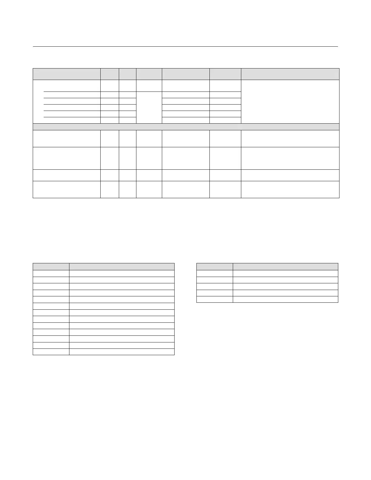
Table 4‐57. Analog Input Block Parameter Definitions (Continued)
Description
Initial
Value
Range
Write Block
Mode
RO /
RW
Index
Number
Label
PARAMETER_NAME
Low Low Alarm
LO_LO_ALM
36
Data Type: DS‐71
The status of the lo lo alarm and its associated time
stamp.
UNACKNOWLEDGED 36.1 RW
N/A
0
ALARM_STATE 36.2 RO 0
TIME_STAMP 36.3 RO 0
SUBCODE 36.4 RO 0
VALUE 36.5 RO 0
Extended Parameter
Output Discrete
OUT_D
37 OOS, MAN OUT_STATE
Data Type: DS‐66
Discrete Output this is true (1) if any of the alarms
selected in ALM_SEL are active.
Alarm Select
ALM_SEL
38 ALL
1: Hi Hi alarm
2: Hi Alarm
3: Lo Lo Alarm
4: Lo Alarm
All bits: 0
Data Type: Bitstring
0=unselected
1=selected
Selected alarms that activate the alarm output.
StdDev
STDDEV
39 RO N/A Positive float
Data Type: Float
Standard deviation of the measurement.
Cap StdDev
CAP_STDDEV
40 RO N/A Positive float
Data Type: Float
Capability standard deviation, the best deviation
that can be achieved.
View Lists
View lists allow the values of a set of parameters to be accessed at the same time. Views 1 and 2 contain operating
parameters and are defined by the Fieldbus Foundation. View 3 contains dynamic parameters and View 4 contains
static parameters with configuration and maintenance information. Views 3 and 4 are defined by the manufacturer.
Table 4‐58. AI Function Block, View 1
Index Number Parameter
1 ST_REV
5.1 MODE_BLK.TARGET_MODE
5.2 MODE_BLK.ACTUAL_MODE
5.3 MODE_BLK.PERMITTED_MODE
5.4 MODE_BLK.NORMAL_MODE
6 BLOCK_ERR
7 PV
8 OUT
19 FIELD_VAL
22.1 ALARM_SUM.CURRENT
22.2 ALARM_SUM.UNACKNOWLEDGED
22.3 ALARM_SUM.UNREPORTED
22.4 ALARM_SUM.DISABLED
Table 4‐59. AI Function Block, View 2
Index Number Parameter
1 ST_REV
10 XD_SCALE
11 OUT_SCALE
12.1 GRANT_DENY.GRANT
12.2 GRANT_DENY.DENY
 Loading...


