EasyGrid User Guide MAN-00084 R 11.0
11
5.6 Action Buttons or State Icons
To help during navigate through the various Settings and Monitoring displays, one basic interface
information is important to know.
Contoured round knobs, for example , are Action Buttons; they allow parameter modification or
function selection.
Round knobs without contour, for example , are State Icons; they simply provide information on the
state of the related parameter or function.
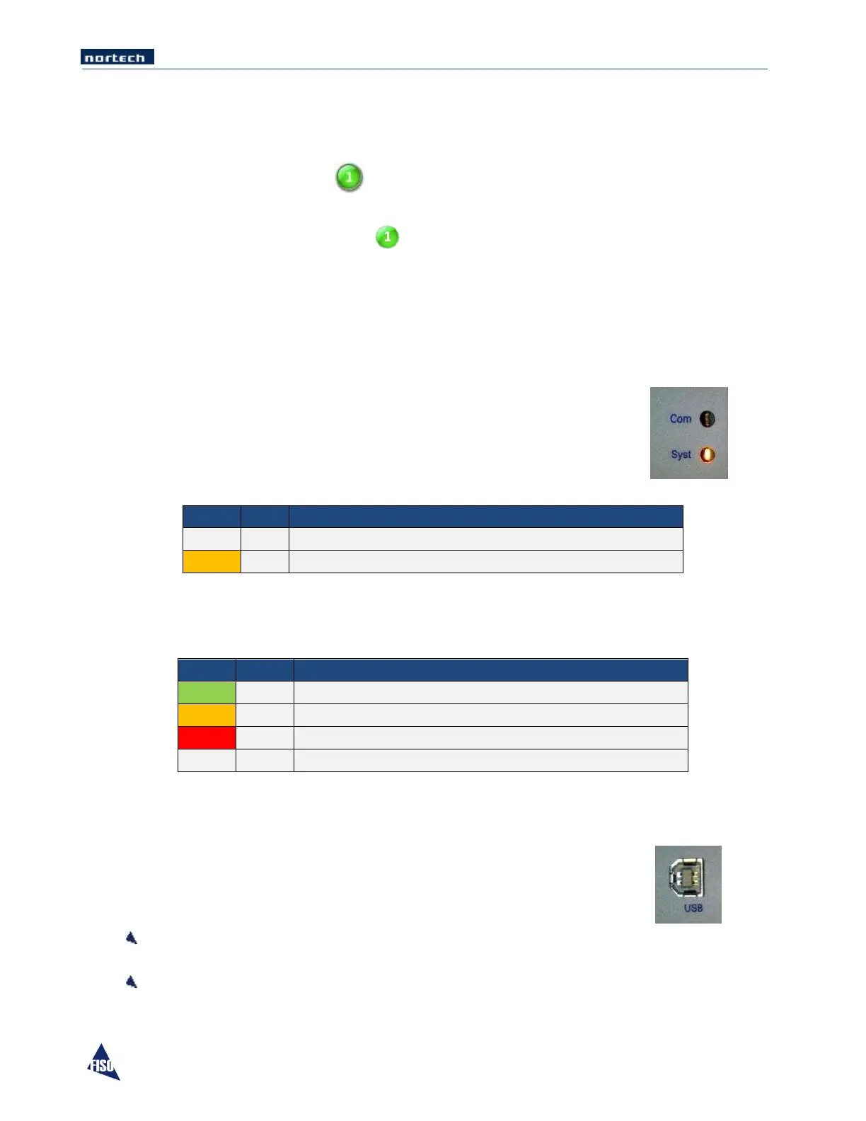
5.7 Communication and System Status LED
The System Status and the Communication Status LED on the front panel change color depending on the
current unit situation.
Communication Status
The different LED modes and their meanings are:
No activity on the communication bus
Activity on the communication bus
System Status
The different LED modes and their meanings are:
MODBUS, IEC or DNP3.0 protocol in function
Nortech protocol in function
System Error or at least one sensor is Faulty
Memory card synchronisation in progress
5.8 USB Configuration Port
The USB configuration interface is accessible in the maintenance panel.
The port serves two purposes:
Communicating with a PC through Nortech Client Software to configure the EasyGrid monitor
parameters, retrieve stored data, upload data or operate the EasyGrid monitor.
Upload updated version of the firmware.