6 Installation
6.2 Transducers FLUXUS F501
2020-06-30, UMFLUXUS_F501V1-3EN
40
• Tighten the cover screws, see Fig. 6.30.
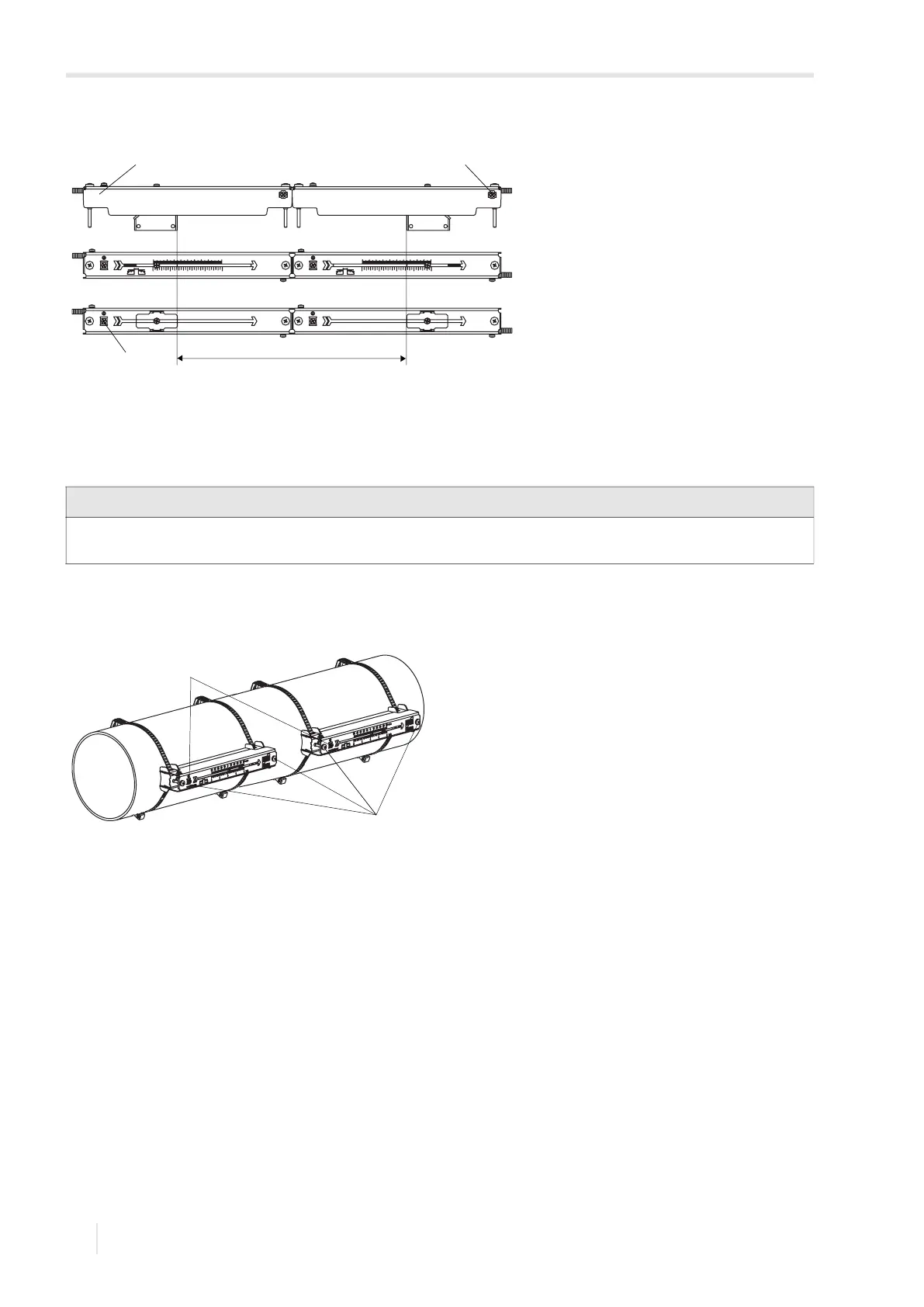
Fig. 6.29: Adjustment of the transducer distance
1 – cover
2 – strain relief clamp
3 – equipotential bonding terminal
a – transducer distance
Notice!
Make sure that the coupling foil remains on the contact surface of the transducers. For information concerning the
coupling foil, see the safety data sheet. In case a safety data sheet is required, contact FLEXIM.
Fig. 6.30: Variofix L with transducers on the pipe
1 – equipotential bonding terminal
2 – cover screws
1 2
a
3
2
1
 Loading...


