7 Connection
FLUXUS G809 7.1 Transducers
71
UMFLUXUS_G809V2-2EN, 2020-06-25
Messumformer FLUXUS G809**-F1
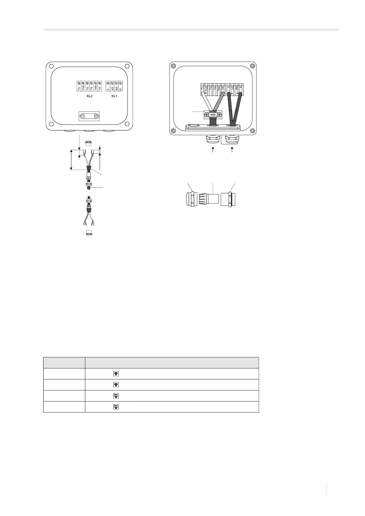
7.1.5 Connection of the transducer cable to the transmitter
• Remove the blind plug for the connection of the transducer cable.
• Insert the transducer cable through the cable conduit (approved for FM Class I, Division 1) into the housing.
• Connect the transducer cable to the terminals of the transmitter, see Fig. 7.10 and Tab. 7.2.
Fig. 7.9: Connection of the extension and transducer cable to the junction box
1 – extension cable
2 – external shield
3 – shield terminal
4 – cap nut
5 – compression part
6 – basic part
7 – connection of the extension cable
8 – connection of the transducer cable
Tab. 7.8: Terminal assignment
terminal connection
AV transducer (core)
AVS transducer (internal shield)
ARS transducer (inner shield)
AR transducer (core)
cable gland
4 5 6
100 mm
20 mm
10 mm
1
2
3
7 8