7 Connection
7.1 Transducers FLUXUS G809
2020-06-25, UMFLUXUS_G809V2-2EN
72
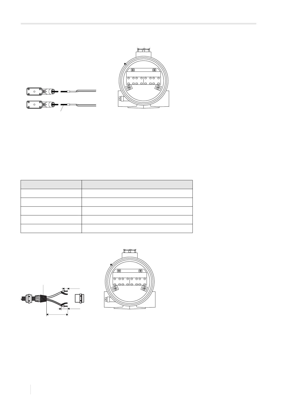
7.1.6 Connection of the extension cable to the transmitter
The extension cable is connected to the transmitter via the transducer connection.
• Remove the blind plug for the connection of the transducer cable.
• Insert the extension cable through the cable conduit (approved for FM Class I, Division 1) into the housing.
• Prepare the extension cable.
• Connect the extension cable to the terminals of the transmitter, see Fig. 7.11 and Tab. 7.9.
Fig. 7.10: Connection of the transducer cable to the transmitter
1 – transducer cable
Tab. 7.9: Terminal assignment
terminal connection
AV white or marked cable (core)
AVS white or marked cable (internal shield)
ARS brown cable (internal shield)
AR brown cable (core)
equipotential bonding terminal external shield
Fig. 7.11: Connection of the extension cable to the transmitter
1 – external shield brushed back
AR ARS AVAVS BR BRS BVBVS
1
70 mm
20 mm
10 mm
1
AR ARS AVAVS BR BRS BVBVS