7 Connection
FLUXUS G809 7.1 Transducers
73
UMFLUXUS_G809V2-2EN, 2020-06-25
7.1.7 Connection to the junction box
Transducer and extension cables are connected via the terminal board KFM1. The terminal board has to be installed into
a junction box (by the customer) approved for the use in explosive atmospheres.
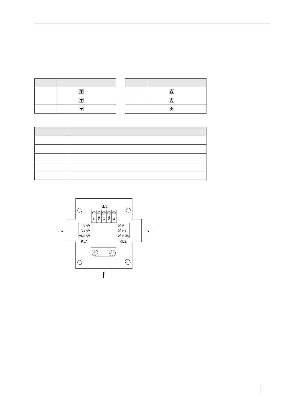
• Connect the transducer and extension cable to the terminals of the junction box, see Tab. 7.10, Tab. 7.11 and Fig. 7.12.
Tab. 7.10: Terminal assignment (transducer cable)
terminal connection (KL1) terminal connection (KL2)
V transducer (core) R transducer (core)
VS transducer (internal shield) RS transducer (internal shield)
VOS transducer (external shield) ROS transducer (external shield)
Tab. 7.11: Terminal assignment (extension cable)
terminal connection (KL3)
TV core
TVS internal shield
TOS external shield
TRS internal shield
TR core
Fig. 7.12: Terminal board KFM1
1 – connection of the transducer cable
2 – connection of the extension cable
1 1
2