FLUXUS WW 10 Basic measurement
76 UMFLUXUS_WWV1-1EN, 2018-02-28
10.5.2 Consistency check
If a wide range for the sound speed has been entered in the program branch Parameter or the exact parameters of the
fluid are unknown, a consistency check is recommended.
The transducer distance can be displayed during the measurement by scrolling the key .
The optimum transducer distance is calculated on the basis of the measured sound speed. It is therefore a better approx-
imation than the first recommended value which had been calculated on the basis of the sound speed range entered in the
program branch Parameter.
If the difference between the optimum and entered transducer distance is less than specified in Tab. 10.1, the measure-
ment is consistent and the measured values are valid. The measurement can be continued.
If the difference is greater, adjust the transducer distance to the displayed optimum value. Afterwards, check the signal
quality and the signal amplitude bar graph (see section 10.5.1). Press ENTER.
Repeat the steps for all channels on which a measurement is made.
10.5.3 Value of the sound speed
The sound speed of the fluid can be displayed during the measurement by pressing key .
If an approximate range for the sound speed has been entered in the program branch Parameter and the transducer dis-
tance has been optimized afterwards as described in section 10.5.2, it is recommended to write down the sound speed for
the next measurement. By doing this, it will not be necessary to repeat the fine adjustment.
Write down the fluid temperature as the sound speed depends on it. The value can be entered in the program branch Pa-
rameter.
The optimum transducer distance is displayed in brackets (here: 50.0 mm) in the upper
line, followed by the entered transducer distance (here: 54.0 mm). The latter value has to
correspond to the adjusted transducer distance. Press ENTER to optimize the transducer
distance.
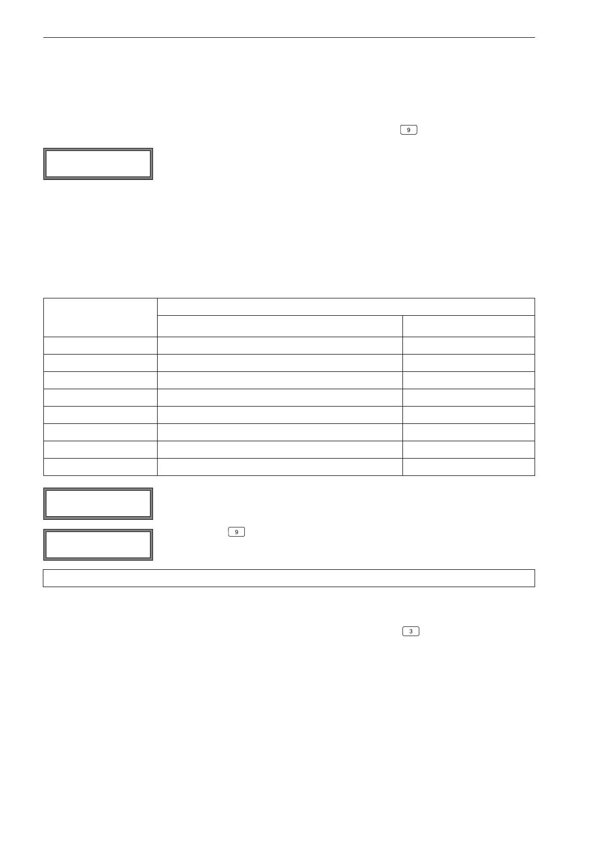
Tab. 10.1: Standard values for signal optimization
transducer frequency
(3rd character of the
technical type)
difference between the optimum and the entered transducer distance [mm]
shear wave transducer Lamb wave transducer
F - -60…+120
G 20 -45…+90
H - -30…+60
K 15 -20…+40
M 10 -10…+20
P8 -5…+10
Q 6 -3…+5
S3 -
Enter the new adjusted transducer distance. Press ENTER.
Scroll with key until the transducer distance is displayed and check the difference be-
tween optimum and entered transducer distance. Repeat the steps, if necessary.
Note!
L=(50.0) 54.0 mm
54.5 m3/h
Transd. Distance?
50.0 mm
L=(51.1) 50.0 mm
54.5 m3/h