8 Connection FLUXUS WW
UMFLUXUS_WWV1-1EN, 2018-02-28 65
8.5 Sensor module (SENSPROM)
The sensor module contains important transducer data for the operation of the transmitter with the transducers.
With transducers of the connection system TS, the sensor module is supplied separately. The transducer module is al-
ready connected to the terminals of the transmitter when delivered (see Fig. 8.16).
If transducers are replaced or added, the sensor module has to be replaced or added, too.
• Disconnect the transmitter from the power supply.
• Insert the sensor module into the lower row of terminal strip (see Fig. 8.1 and Fig. 8.17). The slots SA1...SA4 are as-
signed to the transducers of measuring channel A, the slots SB1...SB4 are assigned to the transducers of measuring
channel B.
• Connect the transmitter to the power supply.
• Enter all parameters of the program branch Parameter.
• Press ENTER until the main menu is displayed again.
Attention! Observe the "Safety instructions for the use in explosive atmospheres" (see SIFLUXUS document).
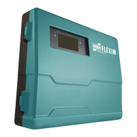
Fig. 8.16: Transmitter FLUXUS WW
(connection system TS)
Note! The serial numbers of the sensor module and the transducer have to be identical. A wrong or incor-
rectly connected sensor module will result in incorrect measured values or in measurement failure.
Fig. 8.17: Transmitter FLUXUS WW
AVSAV
AGN
ARS
AR
BVSBV
BGN
BRS
BR
SA1
SA2
SA3
SA4
SB1
SB2
SB3
SB4
T1a
T1b
S2 T2a
T3a
T3b
S4
T4a
T2b
T4b
T1A
T1B
S1 T2A
T3A
T3B
S3
T4A
T2B
T4B
A+
B-
P1+ P2+
P4+
P5a
P6a P7a
P3+
101
103
P1- P2-
P4-
P5b
P6b
P7b
P3-
PE
N(-)
L(+)
AVSAV
AGN
ARS
AR
BVSBV
BGN
BRS
BR
SA1
SA2
SA3
SA4
SB1
SB2
SB3
SB4
T1a
T1b
S2 T2a
T3a
T3b
S4
T4a
T2b
T4b
T1A
T1B
S1 T2A
T3A
T3B
S3
T4A
T2B
T4B
A+
B-
P1+ P2+
P4+
P5a
P6a P7a
P3+
101
103
P1- P2-
P4-
P5b
P6b
P7b
P3-
PE
N(-)
L(+)
sensor module
measuring channel A
sensor module
measuring channel B
 Loading...


