8 Connection FLUXUS WW
UMFLUXUS_WWV1-1EN, 2018-02-28 63
8.3 Outputs
For the connection of the output cable to the transmitter, see box "Cable connection" p. 62,
Fig. 8.14 and Tab. 8.11
.
1
For the setting of the switching condition, see section 16.1.
Attention! Observe the "Safety instructions for the use in explosive atmospheres" (see SIFLUXUS document).
Attention! The outputs can only be connected to a low voltage circuit (max. 30 V AC or 42 V DC against earth).
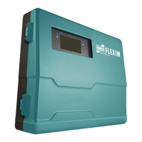
Fig. 8.14: Transmitter FLUXUS WW
Tab. 8.11: Konfiguration der Ausgänge
output transmitter external circuit remark
internal circuit connection
switchable current
loop
1
All switchable cur-
rent outputs are
switched to active or
passive mode at the
same time.
Px+
Px-
active current loop:
R
ext
< 350 Ω
Px+
Px-
passive current loop:
U
ext
=
8...30 V
U
ext
> 0.021 A
.
R
ext
[Ω] + 8 V
example:
U
ext
= 12 V
R
ext
= 0...190 Ω
binary output
(optorelay)
Pxa
Pxb
U
ext
≤ 26 V
I
c
≤ 100 mA
RS485
A+
B-
120 Ω
termination resistor
shield 101
The number, type and connections of the outputs are customized.
R
ext
is the sum of all ohmic resistances in the circuit (e.g. resistance of the conductors, resistance of the ampere-
meter/voltmeter).
AVSAV
AGN
ARS
AR
BVSBV
BGN
BRS
BR
SA1
SA2
SA3
SA4
SB1
SB2
SB3
SB4
T1a
T1b
S2 T2a
T3a
T3b
S4
T4a
T2b
T4b
T1A
T1B
S1 T2A
T3A
T3B
S3
T4A
T2B
T4B
A+
B-
P1+ P2+
P4+
P5a
P6a P7a
P3+
101
103
P1- P2-
P4-
P5b
P6b
P7b
P3-
PE
N(-)
L(+)
cable gland
cap nut
compression part basic part
outputs
 Loading...


