16 Outputs FLUXUS WW
UMFLUXUS_WWV1-1EN, 2018-02-28 119
16.6 Behavior of the alarm outputs
16.6.1 Apparent switching delay
The measured values and the totalizer values will be displayed rounded to 2 decimal places. The limits, however, will be
compared to the non-rounded measured values. This might cause an apparent switching delay when the measured value
changes marginally (less than 2 decimal places). In this case the switching accuracy of the output is higher than the accu-
racy of the display.
16.6.2 Reset and initialization of the alarms
After an initialization of the transmitter all alarm outputs will be configured as follows:
Press three times key C during measurement to set all alarm outputs to the idle state. Alarm outputs whose switching con-
dition is still met will be activated again after 1 s. This function is used to reset alarm outputs of the type HOLD if the switch-
ing condition is no longer met.
By pressing key BRK, the measurement is stopped and the main menu is selected. All alarm outputs will be de-energized,
independently of the programmed idle state.
16.6.3 Alarm outputs during transducer positioning
At the beginning of the transducer positioning (bar graph display), all alarm outputs switch back to the programmed idle
state.
If the bar graph is selected during measurement, all alarm outputs will switch back to the programmed idle state.
An alarm output of the type HOLD that has been activated during the previous measurement will remain in the idle state af-
ter the transducer positioning if the switching condition is no longer met.
The switching of the alarms into the idle state will not be displayed.
16.6.4 Alarm outputs during measurement
An alarm output with switching condition MAX or MIN will be updated max. once per second to avoid humming (i.e. fluctua-
tion of the measured values around the value of the switching condition).
An alarm output of the type NON-HOLD will be activated if the switching condition is met. It will be deactivated if the switch-
ing condition is no longer met. The alarm will remain activated for at least 1 s even if the switching condition is met for a
shorter period of time.
Alarm outputs with the switching condition QUANT. will be activated if the limit is reached.
Alarm outputs with the switching condition ERROR will only be activated after several unsuccessful measuring attempts.
Therefore, typical short-term disturbances of the measurement (e.g., switching on of a pump) will not activate the alarm.
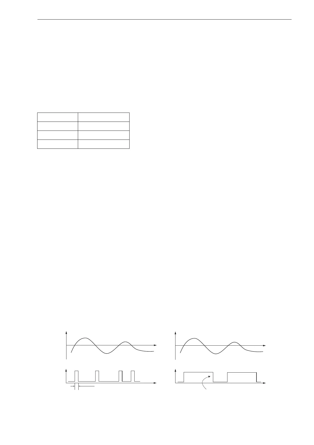
Alarm outputs with the switching condition +→- -→+ and the type NON-HOLD will be activated with each change of the flow
direction for approx. 1 s (see Fig. 16.2).
Alarm outputs with the switching condition +→- -→+ and of the type HOLD will be activated after the first change of the flow
direction. They can be switched back by pressing key C 3 times (see Fig. 16.2).
Tab. 16.5: Alarm state after an initialization
func OFF
typ NON-HOLD
mode NO Cont.
Limit 0.00
Fig. 16.2: Behavior of a relay when the flow direction changes
flow
type NON-HOLD type HOLD
reset of the alarm
(3x key C)
approx. 1 s
flow