APU OPERATION
General
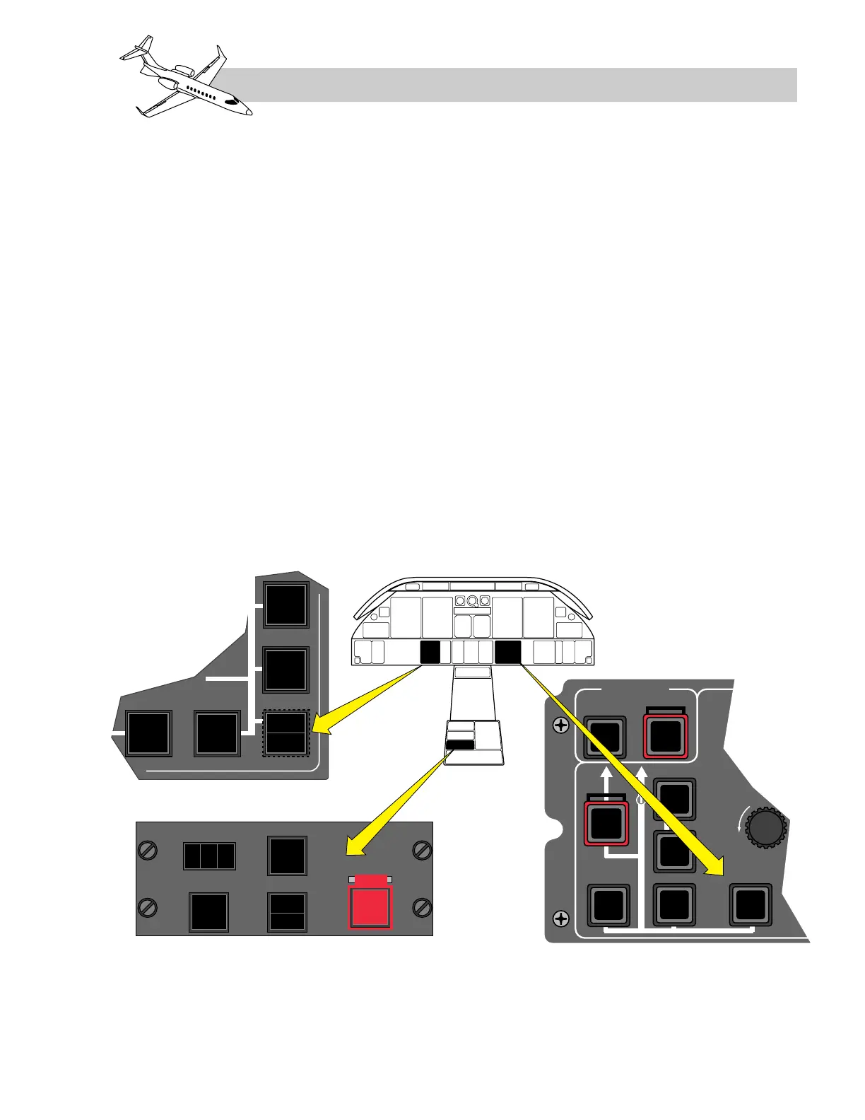
Operation of the APU is provided through the
APU control panel located on the cockpit cen-
ter pedestal, the APU Bleed S/I on the pres-
surization control panel, and the APU GEN S/I
on the electrical control panel (Figure 6-8).
Electronic Control Unit (ECU)
The electronic control unit (ECU) is a fully au-
tomatic, digital unit, located in the tailcone.
The ECU is the interface for receiving inputs
and sending the required output signals to
safely start, operate and shutdown the APU.
The following functions are controlled by the
ECU:
• Start sequence
• Acceleration timing
• On-speed governing
• Normal shutdown
• Fault detection and fault logging
• Connection to other aircraft subsystems
APU Starting System
When the APU MASTER S/I (Figure 6-8) is
pressed, the ECU power supply is activated and
initiates an internal test mode. The operator
must wait at least 10 seconds after pressing the
APU MASTER S/I before pressing the mo-
mentary START S/I. This allows the ECU to
complete the power-up and test modes.
Following the BITE test, the APU
START/STOP S/I on the cockpit panel is
pressed to initiate the start. The white
“START” caption is illuminated in the
switch/indicator by the ECU and remains on
for the entire start sequence.
6-7
FOR TRAINING PURPOSES ONLY
LEARJET 45 PILOT TRAINING MANUAL
FlightSafety
international