ELECTRICAL SYSTEM
INDICATORS
Monitoring of the DC electrical system is
menu selectable on the EICAS or MFD dis-
plays (Figure 2-10). Electrical system pa-
rameters are usually monitored on the EICAS
SUMRY page. The SUMRY display is the
power-up default display on the EICAS and
MFD. Electrical system parameters in the form
of a system schematic may also be monitored
on the ELEC system schematic on the EICAS
or MFD (Figure 2-13).
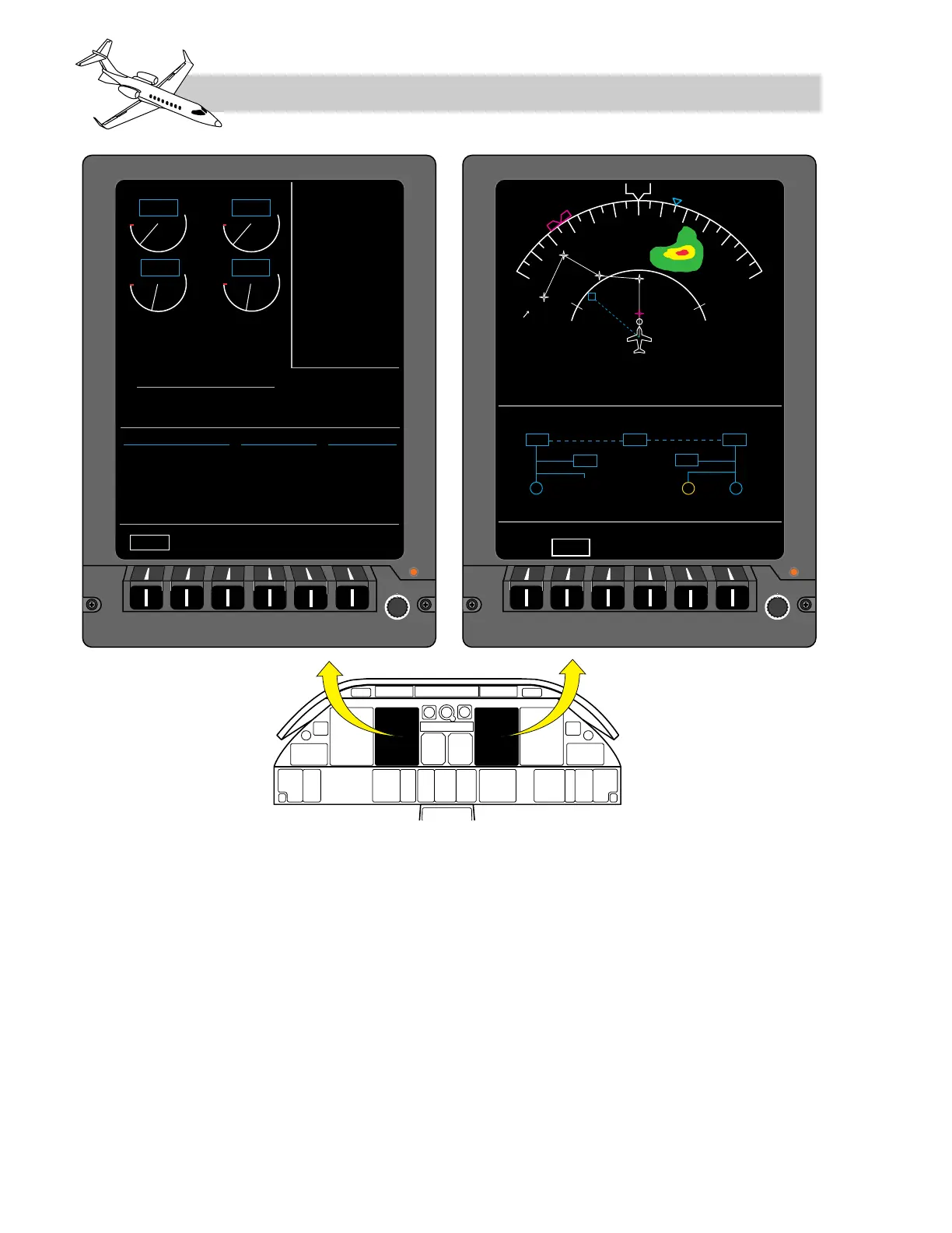
Electrical system volts and amps may also be
selected for display on either RMU (Figure 2-
11). Under some conditions (e.g. dual IC 600
failure or power loss), the No.1 RMU will au-
tomatically display the first of two backup
engine pages, which provide engine operating
indications and other systems data normally
LEARJET 45 PILOT TRAINING MANUAL
2-12
FOR TRAINING PURPOSES ONLY
FlightSafety
international
SYSTEM SCHEMATIC.