ELECTRICAL CONTROL
PANEL
GENERAL
The electrical switches and indicators include
an electrical switch panel layout designed to
control the electrical system and show system
interconnect (Figure 2-9), two circuit breaker
panels and selectable system monitoring dis-
plays on the EICAS, MFD and RMUs.
The DC power system electrical control panel
is designed to provide ease of operation and
dark cockpit integration. The automatic load
shedding design for operation with single or
dual generator failure relieves the pilot of
manual deselection of electrical busses to pre-
vent an overload. The control panel reflects and
displays batteries, generators, or busses that
have been isolated (automatically shed) in the
event of a fault. The pilot has a manual over-
ride option of selecting, recycling or dese-
lecting some of the busses on the DC system.
During engine start, the generator auto-start
feature reduces engine start switch selections
and pilot workload.
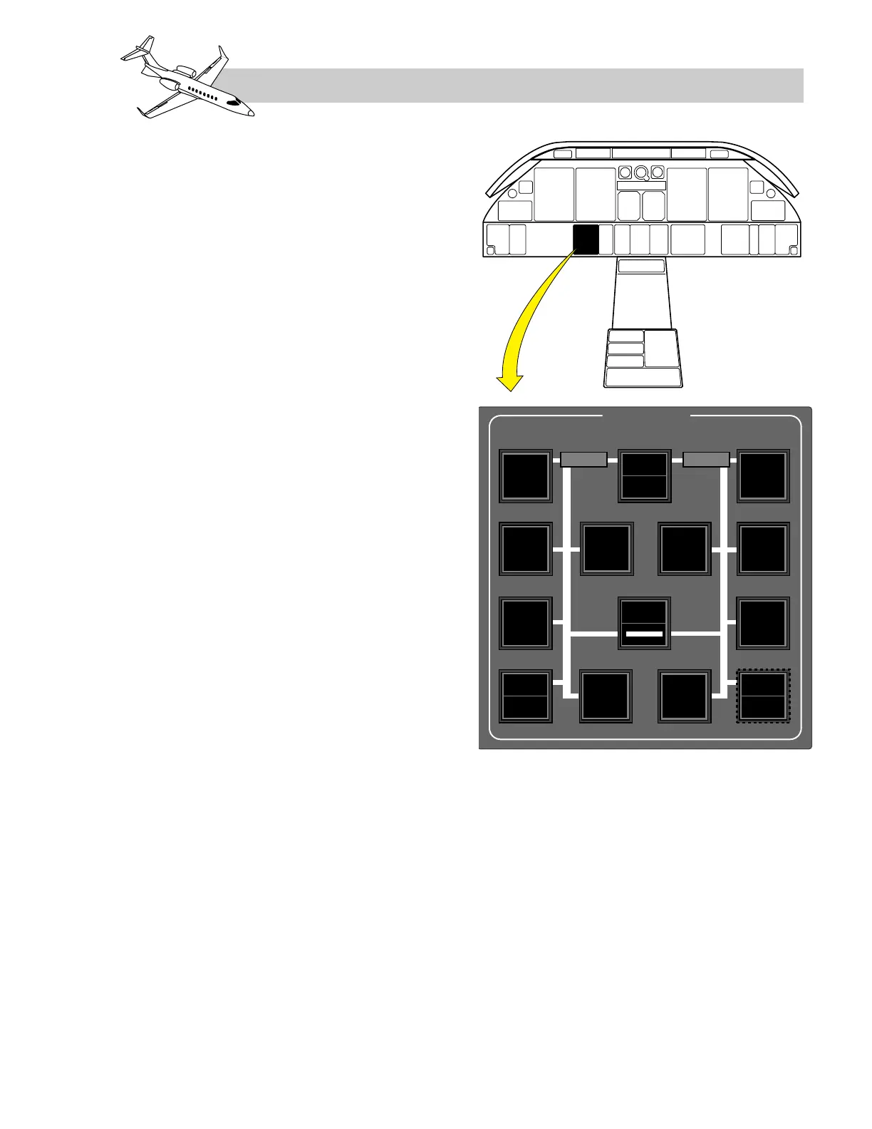
The electrical control panel (Figure 2-9)con-
sists of an illuminated panel with 13 (14 when
an APU is installed) switched S/Is. All cap-
tions have white letters on a black background
except for “AVAIL” on the GPU and APU
switches, which are green on a black back-
ground. For normal flight conditions, none of
the switch captions should be illuminated.
LEARJET 45 PILOT TRAINING MANUAL
2-9
FOR TRAINING PURPOSES ONLY
FlightSafety
international