INTRODUCTION
The fire protection system consists of fire detector sensing elements for each engine and APU
(if installed), fire detect control units located in the tailcone, engine fire and APU indicator
lights on the center pedestal, two engine fire and one APU extinguisher bottles (cockpit ac-
tivated) located in the tailcone, and a fire detector and extinguisher circuit test. The engine
fire alerting system includes an engine fire voice message, an engine fire annunciation on
the EICAS and illumination of the master warning lights with accompanying chime. The APU
fire warning system includes a horn located in the nose wheel well.
ENGINE FIRE DETECTION
The fire detection system for each engine con-
sists of heat sensing elements, a control unit
and a warning light. Each engine cowling con-
tains three heat sensing elements connected to
the fire detection control units. Each control
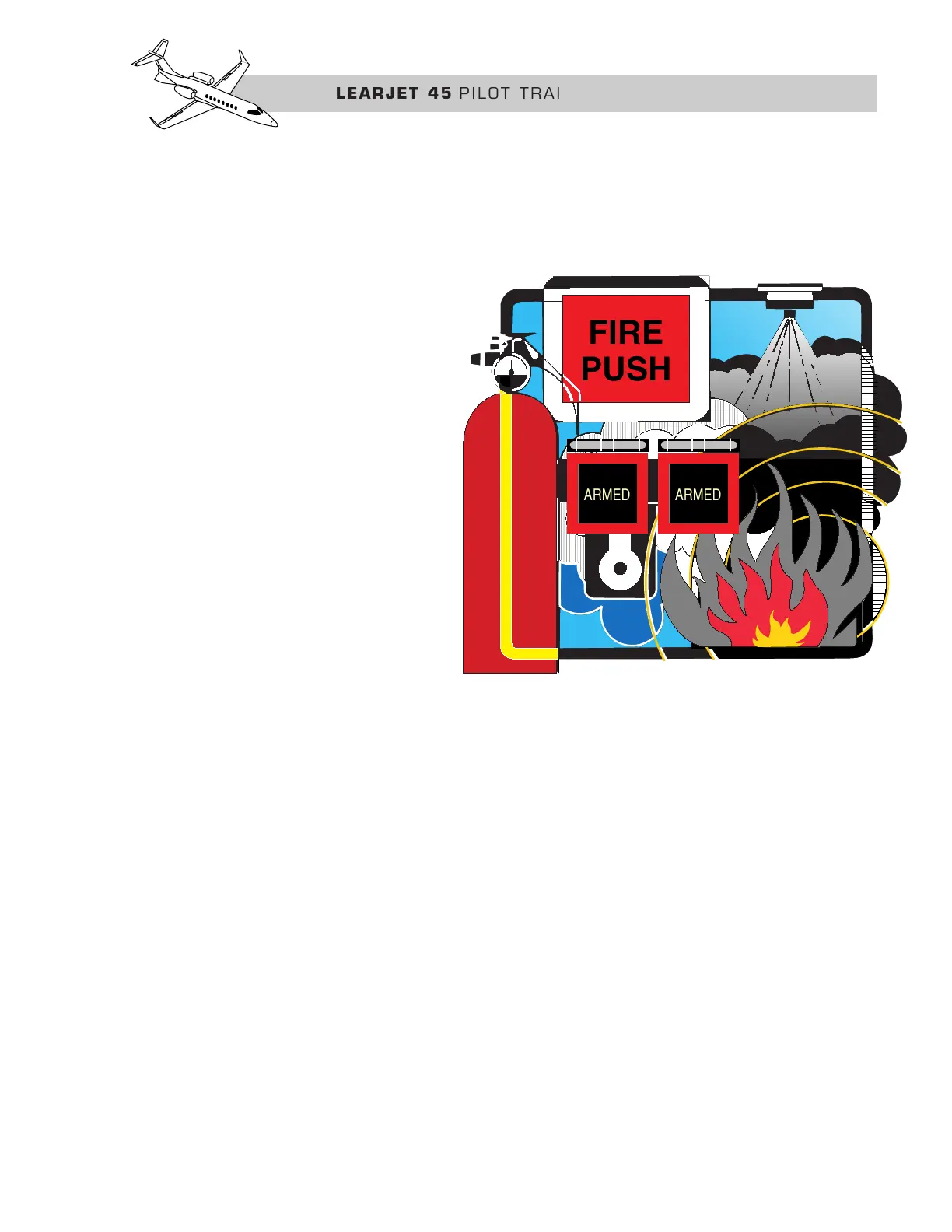
unit is then connected to respective engine
FIRE PUSH switch/indicators located on the
center pedestal engine/fuel control panel
(Figure 8-1) and to the CWP.
The engine fire detection control units moni-
tor the electrical resistance of three sections
of sensing elements and energize the engine
fire alerting system when the temperature in