EICAS Engine Indications (EIs)
Listed below are the indications that can ap-
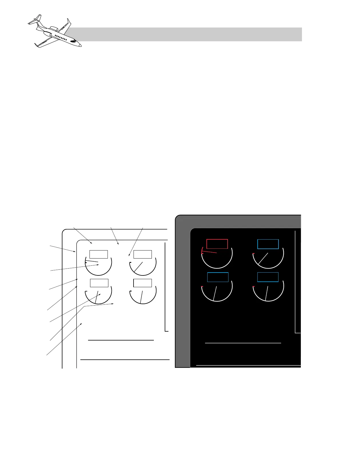
pear on the EICAS display in the engine field.
See Figure 7-8 for the location of the indica-
tions and Table 7-3 for the logic that deter-
mines when the indicators will be displayed
and their color coding. Notice that several of
the indications can appear as different colors
dependent on the status of the system.
• Fan Sync (SYNC)
• Turbine Sync (SYNC)
• Ignition (IGN)
• Thrust reverser status (REV, UNL, DEP)
• Thrust lever position (MCR, MCT, T/O)
• Automatic power reserve status (APR)
• Nacelle heat status (NAC)
• Engine starter engaged (START)
• Fuel control mode (MAN)
ENGINE CAS MESSAGES
The top, right section of the EICAS display
format is dedicated to the crew alerting sys-
tem (CAS). The CAS can present caution,
warning and advisory messages on all aircraft
systems. This chapter will only discuss the
engine and thrust reverser related messages.
LEARJET 45 PILOT TRAINING MANUAL
7-12
FOR TRAINING PURPOSES ONLY
FlightSafety
international
 Loading...