Battery starts may be made at temperatures
above 0°C. Engine starts should be made with
the use of a GPU or APU in temperatures from
0°C or below.
EMERGENCY BATTERY
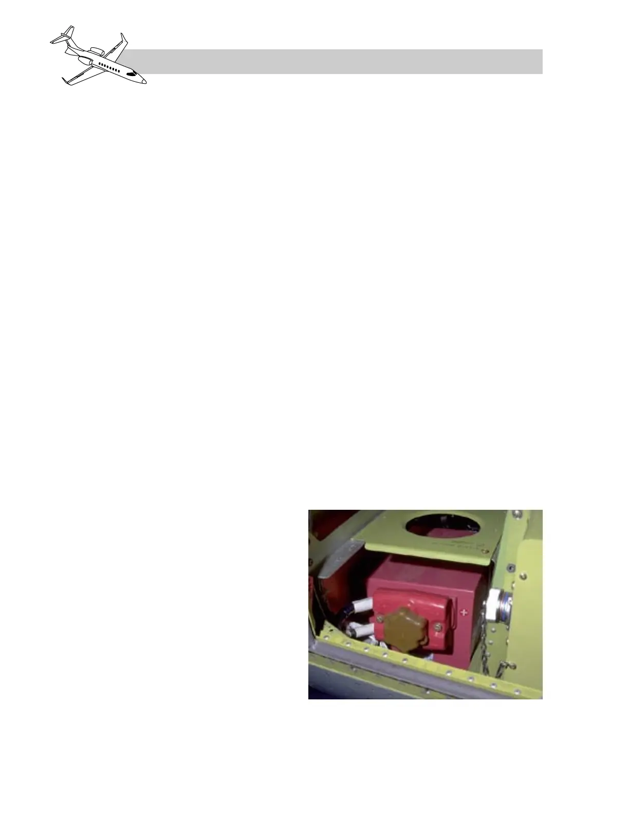
The standard emergency battery is one 24
VDC, 10 amp/hour, lead-acid which is located
in the nose section of the airplane (Figure 2-
4). The duration of the emergency battery is
approximately 1 hour for operation of mini-
mum essential equipment in the event of dual
generator failure in flight.
The emergency battery is connected to the
emergency battery bus when selected ON, but
only provides power to that bus when the elec-
trical system is not being powered by a GPU,
APU or airplane generator (Figure 2-18). The
emergency battery also provides power to both
emergency hot busses even with the emer-
gency battery selected OFF. The emergency
battery provides power to the emergency bat-
tery bus in the event of a dual generator fail-
ure or an inflight electrical fire. The
installation also enables the essential and es-
sential avionics busses to be powered by the
emergency battery in isolation from the main
system during the engine start sequence, thus
preventing problems caused by voltage fluc-
tuations during start.
The emergency battery is charged by the air-
plane electrical system and provides power
to the emergency battery bus for a limited
time if the airplane DC generators fail.
A shunt, located between the emergency bat-
tery and the emergency battery contactor allows
for monitoring of battery recharge and dis-
charge current. If the emergency battery is se-
lected to ON and a battery discharge current
is sensed by the shunt, the white EMER cap-
tion on the emergency battery switch (Figure
2-9) will illuminate, indicating emergency bat-
tery discharge. A white EMER BATT annun-
ciator on the CWP will also illuminate for this
condition (Figure 2-12). Battery charging from
the airplane generators precludes these indi-
cations under normal operation. The emer-
gency battery has the same battery depletion
protection on the ground as the main batteries.
The shunt also monitors emergency battery
charging. If it exceeds 10 amps for 15 seconds,
an amber “EMER BATT LOW” message is
displayed on the CAS alerting the crew to an
emergency battery recharging condition. This
message may come on for a short duration
after engine start. The CAS message is sup-
pressed for two minutes after engine start.
The emergency battery voltage can be checked
by observing the EMER-V on the EICAS/MFD
SUMRY page or EMER BUS VOLTS on the
EICAS/MFD ELEC systems schematic dis-
play prior to applying GPU, APU or airplane
generator power to the electrical system.
The items listed beneath EMER BATT BUS in
Table 2-4 are those which are connected di-
rectly to the emergency battery bus and will be
available when that bus is being powered by the
emergency battery, aircraft generator, GPU or
APU. Main airplane batteries alone will not
power the emergency battery bus because the
isolation contactors will both be open if both
generators are off-line and neither an APU or
GPU is powering the electrical system (Figure
2-18).
LEARJET 45 PILOT TRAINING MANUAL
2-4
FOR TRAINING PURPOSES ONLY
FlightSafety
international
Figure 2-4. Emergency Battery Location