ENGINE/FUEL CONTROL
PANEL
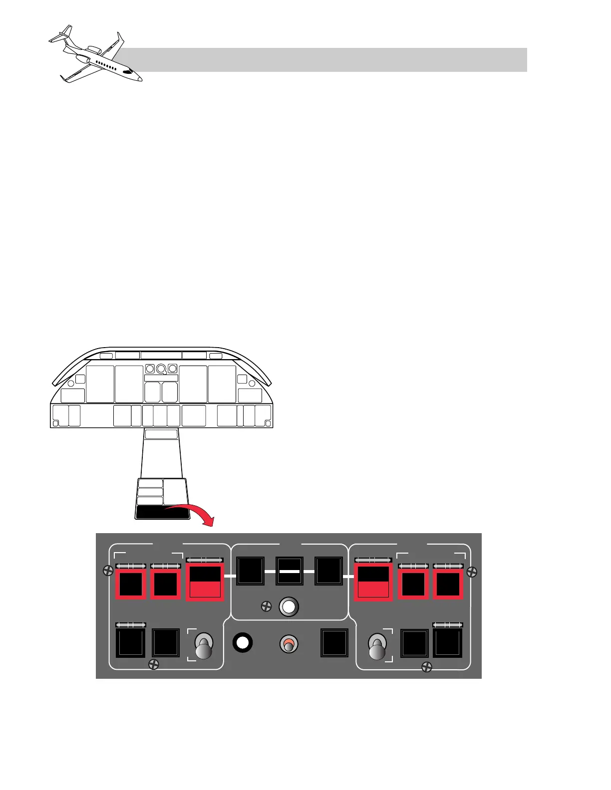
The engine/fuel control panel is located toward
the aft end of the center pedestal (Figure 7-11).
The engine related controls on this panel in-
clude left and right engine start switches, ig-
nition switches and computer switches.
Located in the center of the panel is also an
EDS (engine diagnostic system) record button,
a three position engine sync switch and an
ARM switch for the APR (automatic perfor-
mance reserve). The panel also includes en-
gine fire indicator/FWSOV switches and
engine extinguisher armed switches.
The L and R ENG CMPTR switches are lever-
locking with three positions (ON, MAN,
OFF). The switches normally remain in the
ON position where they provide electrical
power to the DEECs for computer-on opera-
tion. When a computer switch is in the man-
ual (MAN) position electrical power is only
available to those circuits within the com-
puter that control the overspeed solenoid and
for fault monitoring.
THRUST LEVERS
Two thrust levers (Figure 7-12) are located in
a quadrant on the forward section of the cen-
ter pedestal. Thrust reverser levers are pig-
gyback mounted on the thrust levers. The
thrust levers operate in a somewhat conven-
tional manner except the throttle quadrant has
detents in the forward range. Each thrust lever
is connected to a rotary variable differential
transformer (RVDT). In the normal computer-
on mode of operation, PLA (power lever angle)
is transmitted to the DEECs through the
RVDTs.
The throttle quadrant has detents and labels
(Figure 7-12) at the following positions, start-
ing full forward at APR and moving aft:
• APR (automatic performance reserve)
• T/O (take-off thrust)
• MCT (maximum continuous thrust)
LEARJET 45 PILOT TRAINING MANUAL
7-16
FOR TRAINING PURPOSES ONLY
FlightSafety
international