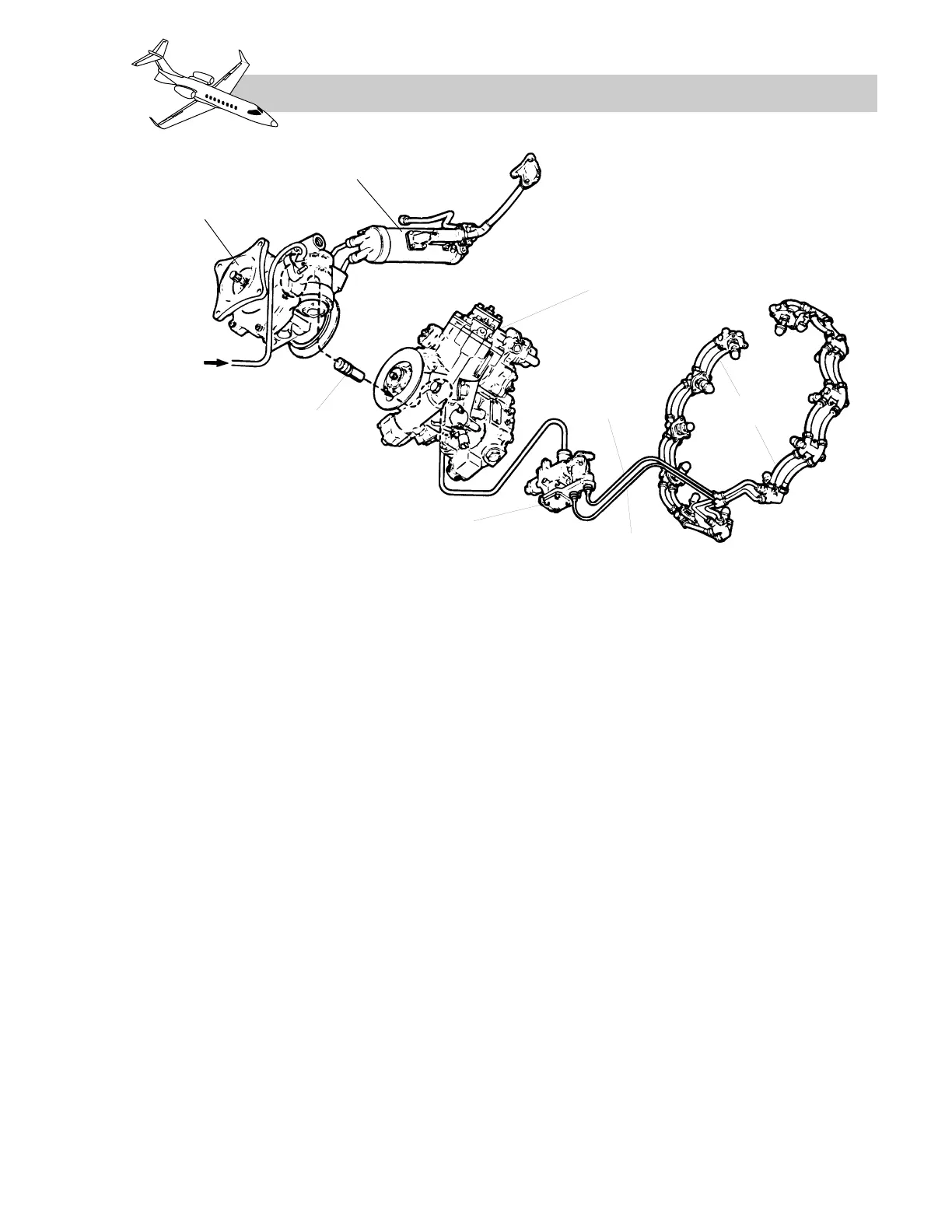
ENGINE FUEL PUMPS
The two-stage engine-driven fuel pump (Figure
7-15) is mounted to the aft left side of the ac-
cessory gearbox. The first stage is a centrifu-
gal pump and the second stage is a high
pressure gear type pump. Fuel pressure is
boosted by the first stage centrifugal pump
and sent through the fuel heater and fuel fil-
ter to the high pressure pump (Figure 7-16).
A separate engine driven motive flow fuel
pump is mounted on the front left side of the
accessary gear box. Its only purpose is to re-
ceive fuel from the wing tank, boost the pres-
sure and return the fuel to the wing tank for
jet pump operation.
FUEL HEATER
The fuel heater (Figure 7-16), which is a heat
exchanger, is installed to prevent fuel icing.
Hot engine oil and engine fuel are routed
through the heat exchanger whereby conduc-
tion both cools the oil and heats the fuel.
Fuel flow through the heat exchanger is con-
tinuous, but if the fuel becomes too hot, a
valve will function to by-pass the hot oil and
limit the fuel temperature. If the fuel temper-
ature exceeds 130° Celsius, a white “L/R FUEL
HEATER” message will be displayed by the
CAS indicating the fuel/oil heat exchanger
has failed to the hot condition.
If the fuel is too cold with fuel temperature less
than 10° C and the oil temperature is greater
than 86° C, an amber “L/R FUEL HEATER”
caution message will be displayed by the CAS
(Table 7-4). If a white FUEL FILTER mes-
sage subsequently appears, there is a possi-
bility of fuel icing.
ENGINE FUEL FILTER
A fuel filter is mounted on the side of the en-
gine fuel pump. Fuel passes through the paper
cellulose filter element (Figure 7-16) as it
flows from the fuel heater to the high pressure
element of the engine pump. Mounted to the
filter housing is an electrical bypass indicat-
ing system. The electrical indicator switch
LEARJET 45 PILOT TRAINING MANUAL
7-21
FOR TRAINING PURPOSES ONLY
FlightSafety
international