circled L, R, and A on the HYD schematic page
represents the three hydraulic pumps. They
turn amber if the corresponding pump output
pressure switch in the main hydraulic manifold
does not detect normal output (1,900 psi). A
“LOW” is annunciated on the system schematic
when the fluid quantity in the auxiliary side of
the reservoir is low (1.2 qt.)(Figure 13-6).
ABNORMAL OPERATION
Hydraulic system malfunctions are displayed
within the CAS window on the EICAS.
Hydraulic system status is also provided on the
RMU, Engine Page 1 (Figure 13-7).
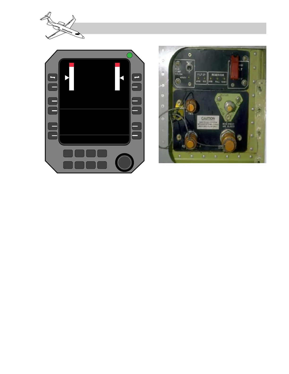
SERVICING
The airplane hydraulic system, main and aux-
iliary, is serviced via the ground service panel
(GSP), located on the right side of the aircraft
(Figure 13-8). The GSP contains a two posi-
tion ground service valve switch, that is po-
sitioned to either GND (ground) or FLT
(flight). When in GND, the valve opens and
allows the auxiliary hydraulic pump or the
engine-driven pumps to power all aircraft sys-
tems (Figure 13-1). Closing the GSP access
door automatically repositions the ground ser-
vice valve to the FLT position.
The auxiliary hydraulic pump DC motor con-
tains brushes. Should the brush wear sensor
detect excessive wear (approximately 90%
worn), an indicator labeled “DC MOTOR
BRUSHES” illuminates on the ground ser-
vice panel (Figure 13-8).
LEARJET 45 PILOT TRAINING MANUAL
13-11
FOR TRAINING PURPOSES ONLY
FlightSafety
international
Figure 13-8. Hydraulic System Ground
Service Panel (GSP)