DIGITAL ELECTRONIC
ENGINE CONTROL (DEEC)
GENERAL
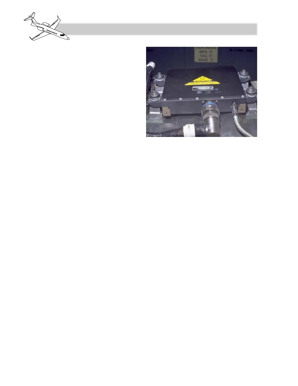
A digital electronic engine control (DEEC),
also referred to as a fuel computer, is located
above the upper portion of the inlet fan hous-
ing assembly on each engine (Figure 7-13).
With the computer switches ON or MAN, the
DEECs receive power from the left and right
essential busses respectively through the L
and R CMPTR circuit breakers located in the
engine group on the left and right circuit
breaker panels.
The DEEC functions to provide the crew with:
• Thrust management
• Rating display – N1 bug reference
• Engine overspeed protection
• Automatic start sequence
• Spool speed and temperature limiting
• Surge-free acceleration and deceleration
• Engine synchronization
• Automatic performance reserve
ENGINE CONTROL
The DEEC controls fuel flow based on thrust
lever position (RVDT) and atmospheric con-
ditions, while maintaining N1, N2, and ITT
within prescribed limits. The DEEC also pro-
vides engine ultimate overspeed protection
and controls the surge bleed valve to prevent
compressor stalls and surges. The DEEC ini-
tiates an automatic start sequence when the
thrust lever is positioned to IDLE and the cor-
responding engine start button is depressed.
This includes automatic fuel enrichment to
200 degrees Celsius ITT.
The DEEC receives input signals representing
the following engine parameters (Figure 7-14).
• N1 (fan speed)
• N2 (turbine speed)
• Thrust lever (RVDT)
• PT2 (inlet pressure)
• TT2 (inlet temperature)
• ITT (interstage turbine temperature)
The N1, N2 and ITT sensors are described in
the ENGINE DISPLAY section of this chap-
ter and the thrust levers (RVDT’s) are de-
scribed under ENGINE CONTROL SYSTEM
in this chapter. Inlet pressure (PT2) and inlet
temperature (TT2) values are obtained by a
sensor probe located in each engine intake,
forward of the fan. These sensor probes are
heated electrically when the NAC HEAT is
turned on.
The DEEC analyzes these signals and pro-
duces output signals which are sent to the
torque motor to control fuel flow, and to two
solenoids for surge bleed valve control. The
DEEC also receives ADC inputs (Mach, alti-
tude, ambient temperature and pressure) and
LEARJET 45 PILOT TRAINING MANUAL
7-18
FOR TRAINING PURPOSES ONLY
FlightSafety
international
Figure 7-13. DEEC on TFE731-20 Engine