ENGINE INSTRUMENTS
GENERAL
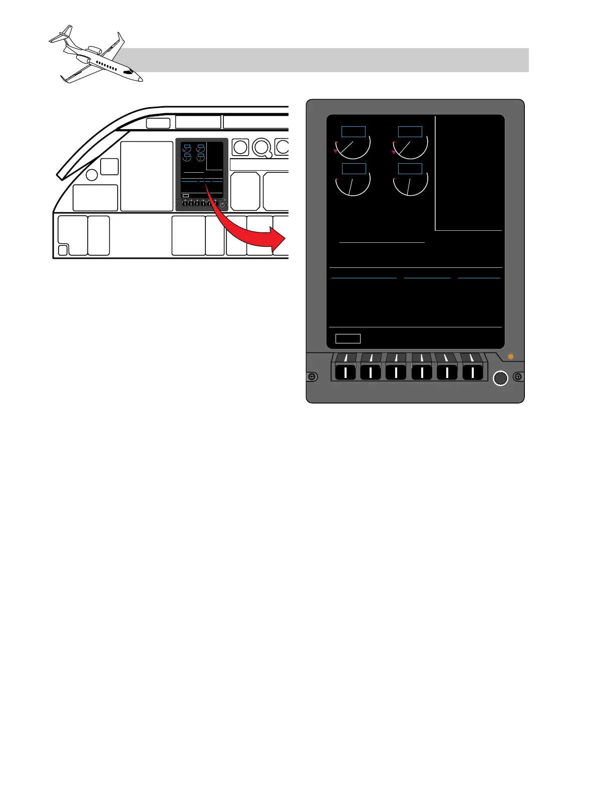
The engine instruments are normally displayed
on the pilot’s inboard display unit (DU2). The
engine instruments are displayed in the top left
quadrant of the DU which is known as the en-
gine field (Figure 7-4).
Two dual channel (CH A and CH B) DAUs
(Data Acquisition Units) collect engine op-
erating information and convert these elec-
trical inputs into ARINC 429 bus format before
transmitting the information to two symbol
generators (SG), one in each IC-600 integrated
computer (Figure 7-5). For redundancy, ei-
ther symbol generator can then display the
engine information on either inboard display
unit (DU2 or DU3), although the left symbol
generator is normally used to display the en-
gine instruments on DU2. The DAUs are dual
channel for redundancy with the left engine in-
puts sent to both channels of the left DAU and
the right engine inputs sent to both channels
of the right DAU. Reversion switches are avail-
able, allowing the pilot to chose which chan-
nel of the DAUs to use, which IC-600 symbol
generator to use and which display unit to dis-
play the EICAS format on.
As a backup to the EICAS, engine indications
can also be displayed on the radio management
units (RMUs) and in some cases this is auto-
matic.
ENGINE DISPLAYS
As illustrated in Figure 7-6, the following is
a list of the left and right engine indicators
shown in the engine field portion of the EICAS:
• N1 - analog fan speed scale with digital
readout.
• ITT - analog interstage turbine temper-
ature with digital readout.
• N2 - digital readout of turbine speed.
• OIL PSI - digital readout of oil pressure.
• OIL °C - digital readout of oil temperature.
• FF PPH - digital readout of fuel flow.
LEARJET 45 PILOT TRAINING MANUAL
7-6
FOR TRAINING PURPOSES ONLY
FlightSafety
international
Figure 7-4. Engine Instrument Display on
the EICAS