• Four vortilons are added to the underside
leading edge to minimize span-wise flow
at high angles of attack.
• A stall strip is attached to each inboard
leading edge near the wing root to ac-
celerate boundary layer separation at
high angles of attack and to provide a
buffet to warn of impending stall (Figure
1-17).
• Eight small triangles are mounted in-
board on each wing leading edge to re-
energize the boundary layer airflow at
high angles of attack (Figure 1-17).
• There are three seams in the wing lead-
ing edge where the skin is offset (saw-
tooth) slightly. The purpose is flow
control (Figure 1-17).
The wing contains track supported Fowler type
flaps, ailerons and spoilerons. The multirole
fly–by–wire spoilers are located on the top
surface of the wing and are used on the ground
for deceleration, inflight as drag devices and
as full-time spoilerons to supplement or replace
normal aileron roll control. The main landing
gear is attached to and housed within the wings.
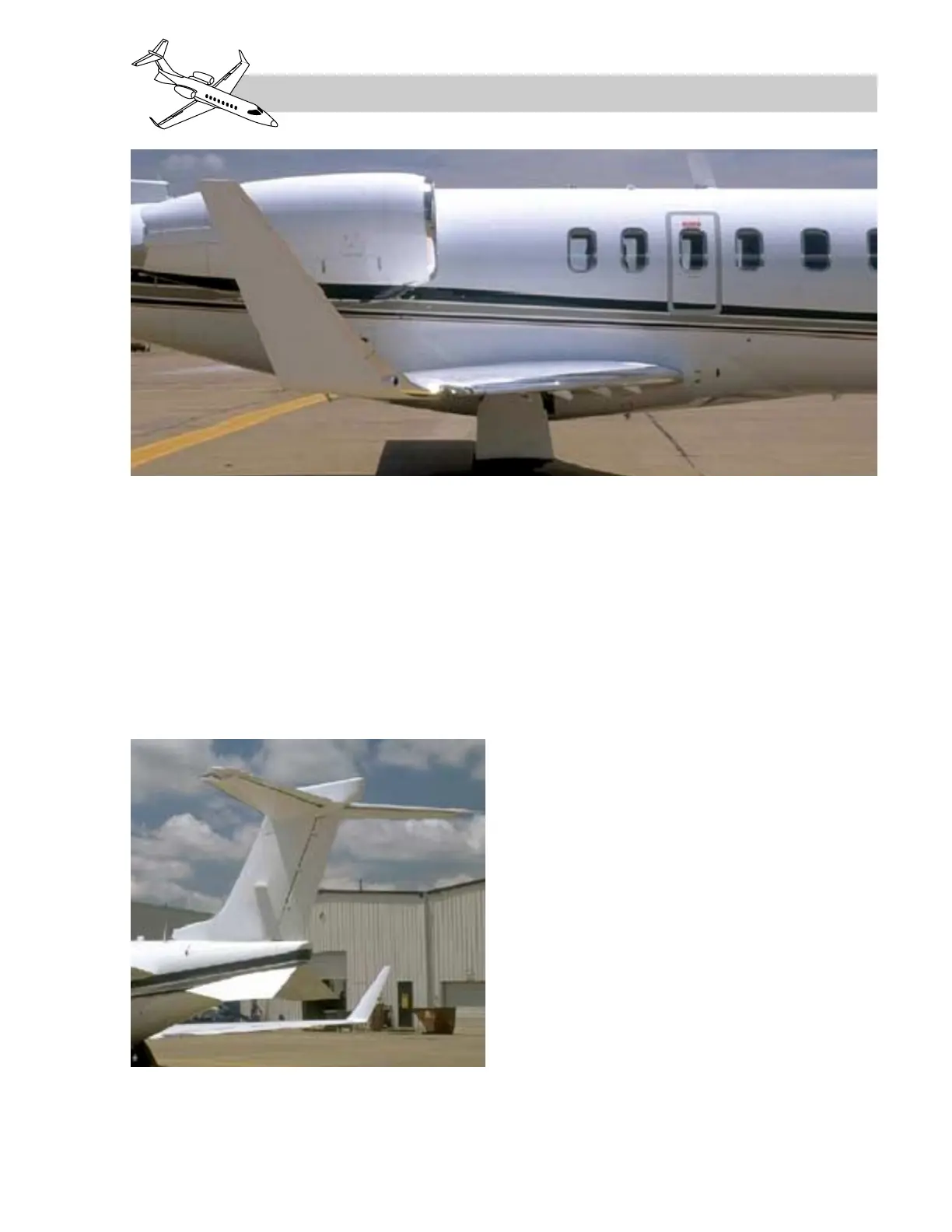
EMPENNAGE
The “T” tail empennage (Figure 1-19) is com-
prised of a dorsal fin, a fixed vertical stabilizer
containing a single rudder with trim tab, a
one–piece moveable horizontal stabilizer, two
elevators attached to the horizontal stabilizer
and two delta fins.
The fiberglass dorsal fin houses the cooling air
intake for ventilation of the tailcone.
LEARJET 45 PILOT TRAINING MANUAL
FlightSafety
international
1-17
FOR TRAINING PURPOSES ONLY
Figure 1-19. Learjet 45 Empennage
Figure 1-18. Learjet 45 Wing