OIL PRESSURE &
TEMPERATURE INDICATIONS
Oil pressure and temperature is sensed in the
oil pressure line between the FHOC and the
fan reduction gearbox. This information is
processed through the DAUs and symbol gen-
erators in the IC-600 computers and is digi-
tally displayed on the EICAS just below the
N
2
indicators (Figure 7-23). The digits will ei-
ther be white, amber or red depending on the
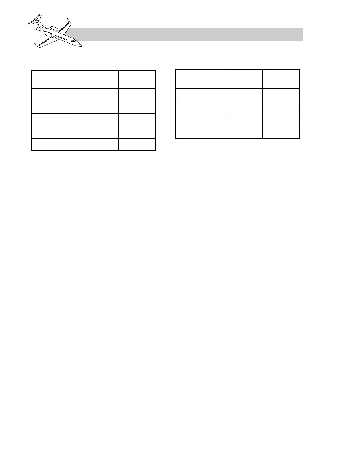
pressure/temperature. See Tables 7-5 and 7-6
for oil indications color coding. Oil temper-
ature is also displayed on page 2 of the engine
pages on either RMU (Figure 7-10).
Any time oil pressure drops below 50 psi, ex-
cept during engine start or when the thrust
lever is in CUTOFF, a red “L/R OIL PRESS
LOW” warning message will be displayed on
the CAS (Figure 7-23). A corresponding red
“L/R OIL PRESS LOW” annunciator will also
illuminate on the CWP when oil pressure is
below 50 psi (Figure 7-23).
ENGINE CHIP DETECTOR
A magnetic chip detection plug is installed in
the scavenge line for detection of metal par-
ticles in the oil. If sufficient metal particles ac-
cumulate on the chip plug while inflight, a
white “L/R ENGINE CHIP” advisory CAS
message will appear on the EICAS (Figure 7-
23). An amber “L/R ENGINE CHIP” CAS ap-
pears if metal particles are detected in the oil
of the respective engine while on the ground.
LEARJET 45 PILOT TRAINING MANUAL
7-32
FOR TRAINING PURPOSES ONLY
FlightSafety
international
not on RMU).
region ends at 125 PSI. The upper red region
starts at 126 PSI.