shown on the EICAS display. The electrical
system volts and amps appear on page 2 of the
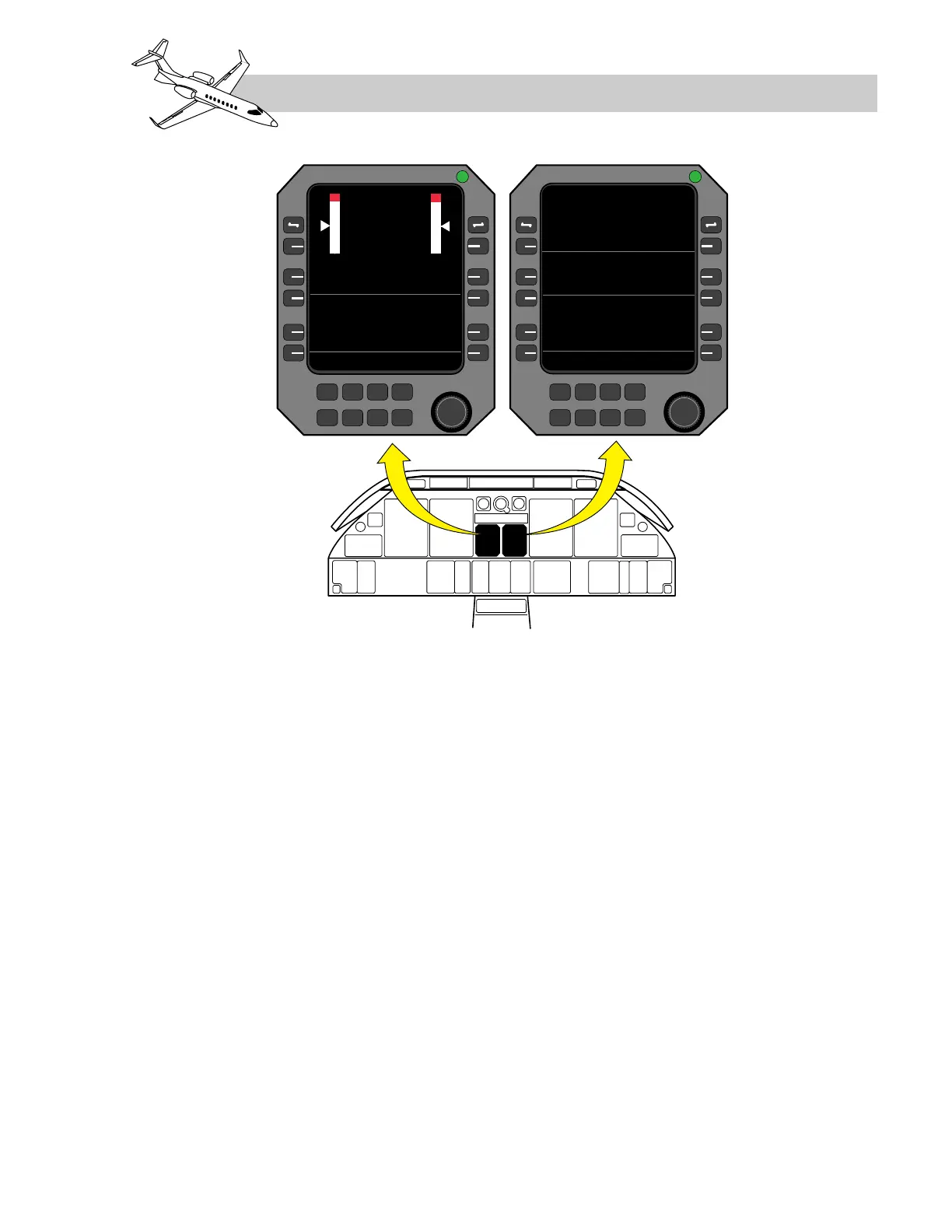
RMU engine displays (Figure 2-11).
Whenever the ENGINE PG1 display is auto-
matically displayed on the No. 1 RMU and
page 2 is subsequently selected, the display re-
turns to page 1 after 20 seconds. Returning the
RMU to the communication and navigation
function is accomplished with the RMU PGE
button. However, if the No.1 RMU is dis-
playing engine information due to an auto-
matic selection, that RMU will return to page
1 of the engine display 20 seconds after the last
pilot selection on the RMU. On the RMU en-
gine displays (page 2), the electrical data will
change color if out of limits, but will not be
boxed.
The EICAS/MFD system SUMRY page
(Figure 2-10) displays VOLTS, left and right.
These two digital displays are an indication of
the voltage on the left and right essential
busses. Depending on what is powering the air-
plane electrical system, this can be an indi-
cation of airplane main battery volts, GPU
volts, APU volts or airplane generator volts.
A “L/R ESS BUS VOLTS” CAS message will
be posted if the voltage on the corresponding
bus decreases below 22 VDC or increases
above 29.5 VDC.
An indication of EMER-V (emergency bus
voltage) is displayed on the SUMRY page im-
mediately below VOLTS, left and right.
Emergency bus voltage can be monitored on
the EICAS/MFD display. The CAS also mon-
itors the emergency bus volts and will gener-
ate an amber “EMER BUS VOLTS” message
LEARJET 45 PILOT TRAINING MANUAL
2-13
FOR TRAINING PURPOSES ONLY
FlightSafety
international