the four stages of LP compression, each stage
becomes smaller, causing a further increase in
pressure until the air reaches the HP section
where a substantial increase in pressure results.
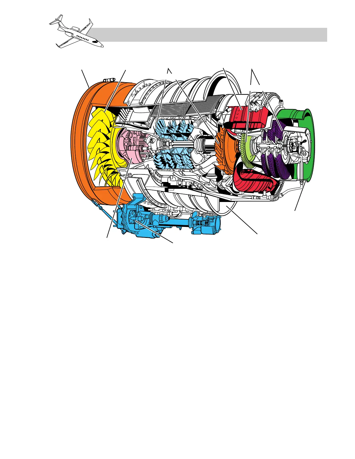
See Figure 7-2.
The HP compressor is contained in the HP
diffuser case and consists of a centrifugal im-
peller. The HP diffuser case, mounted to the
back of the LP case, also contains the drive gear
for the tower shaft, which drives the accessory
gearbox located beneath the engine unit.
Stall-surge protection for the LP compressor
is provided by an automatically controlled
surge bleed valve. This function is controlled
by the digital electronic engine control
(DEEC) and prevents engine stall during rapid
deceleration or acceleration.
Air leaving the HP compressor is then forced
through a transition duct into a plenum cham-
ber surrounding the combustor.
LEARJET 45 PILOT TRAINING MANUAL
7-3
FOR TRAINING PURPOSES ONLY
FlightSafety
international