NOSE GEAR COMPONENTS
General
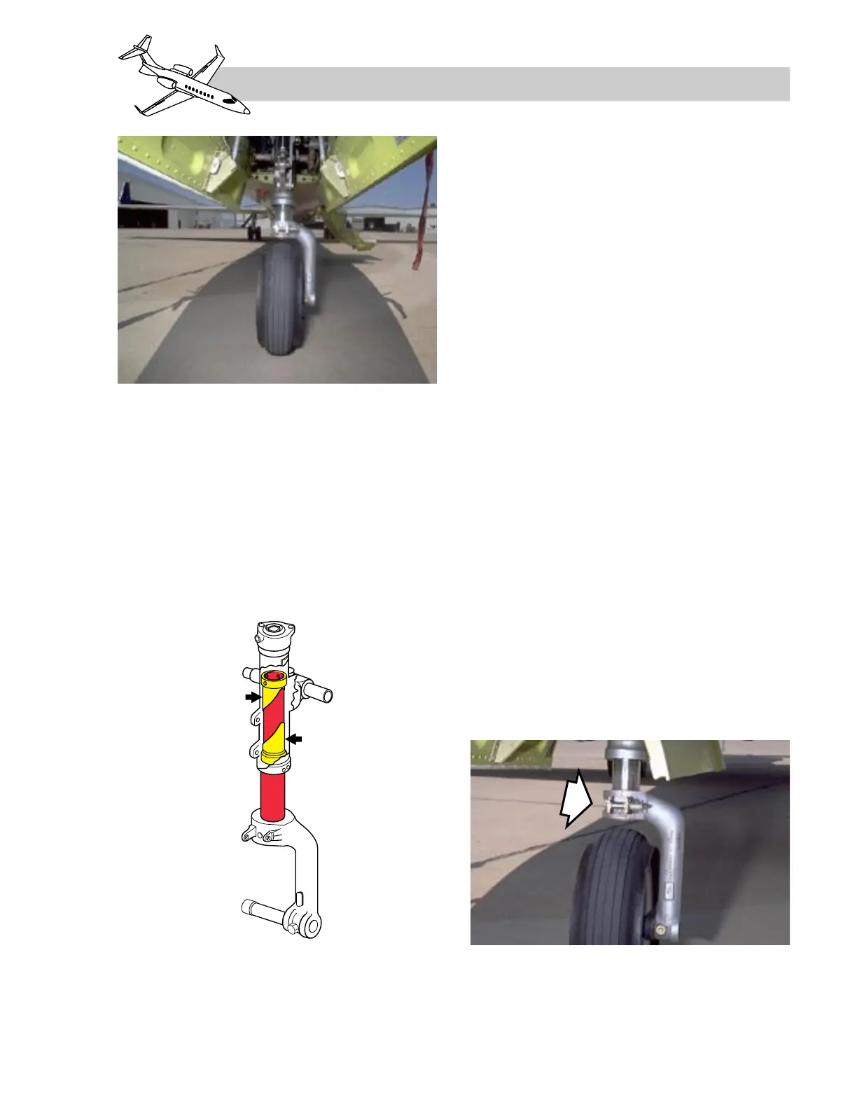
The nose gear consists of an air-hydraulic
shock strut incorporating a self-centering de-
vice, a nosewheel steering actuator, a single
wheel/tire, and mechanically operated doors
(Figure 14-7). The nose strut does not incor-
porate a scissors link.
The nose gear actuator incorporates an inte-
gral downlock mechanism to maintain down-
locked condition; therefore, a downlock pin
is not provided. As with the main gear actu-
ator, the locking mechanism can only be re-
leased by applying hydraulic pressure on the
retract side.
The gear is retracted with positive hydraulic
pressure, then a spring-loaded uplock hook en-
gages the uplatch roller on the forward side
of the strut. When retracted, the nose gear is
enclosed by two doors that are mechanically
connected to, and move with the gear strut.
The uplock hook holds the nose gear up when
hydraulic pressure is relieved after gear re-
traction.
The nose gear uplock can be released by two
methods. The nose gear uplock is hydraulically
operated for normal extension, and is me-
chanically operated via cabling for free-fall ex-
tension.
The nose strut incorporates a mechanism to
center the nose wheel for retraction. At liftoff,
two cams within the strut are engaged by strut
air pressure, centering the wheel before it en-
ters the wheel well (Figure 14-8). Also, the
nose steering computer electrically centers
the wheel after main gear liftoff.
Since nosewheel centering prior to gear re-
traction depends on air pressure in the strut,
proper inflation of the strut is important. As
14-9
FOR TRAINING PURPOSES ONLY
LEARJET 45 PILOT TRAINING MANUAL
FlightSafety
international
LEARJET 45 PILOT TRAINING MANUAL
FlightSafety
international
Figure 14-8. Nose Gear Centering Cams
Figure 14-7. Nose Landing Gear
Figure 14-9. Nose Gear Uplock Roller