The digital displays on the SUMRY and FLT
pages only show spoiler extension that is com-
manded by autospoilers or with the spoiler
lever. They do not reflect differential extension
that is a result of spoileron mode operation.
When the spoilers are extended on the ground
or inflight a white “SPOILERS EXT” CAS
message is displayed. This CAS will only be
displayed when the spoilers are extended by
the autospoiler system or by the spoiler lever.
When the airplane is on the ground and spoil-
ers are extended, a white box will overlay the
digital spoiler displays to bring attention to the
crew. If power is advanced for takeoff with ei-
ther/both spoilers extended, the digital dis-
play and box turn red, the ”SPOILERS EXT”
CAS message turns red and the
“CONFIGURATION” voice message is played.
The pointers on the analog scale will also turn
red in this case.
The analog scale and pointers show actual
spoiler position for all conditions. When the
spoilers are extended different amounts due to
spoileron operation, the pointers will indicate
the differential on the analog scale.
The digital spoiler indicators and the analog
scale pointers will turn amber anytime the
flaps are extended to 3° or more and the spoil-
ers are extended.
There are six EICAS messages that provide
spoiler/spoileron system operation status. See
Table 15-1.
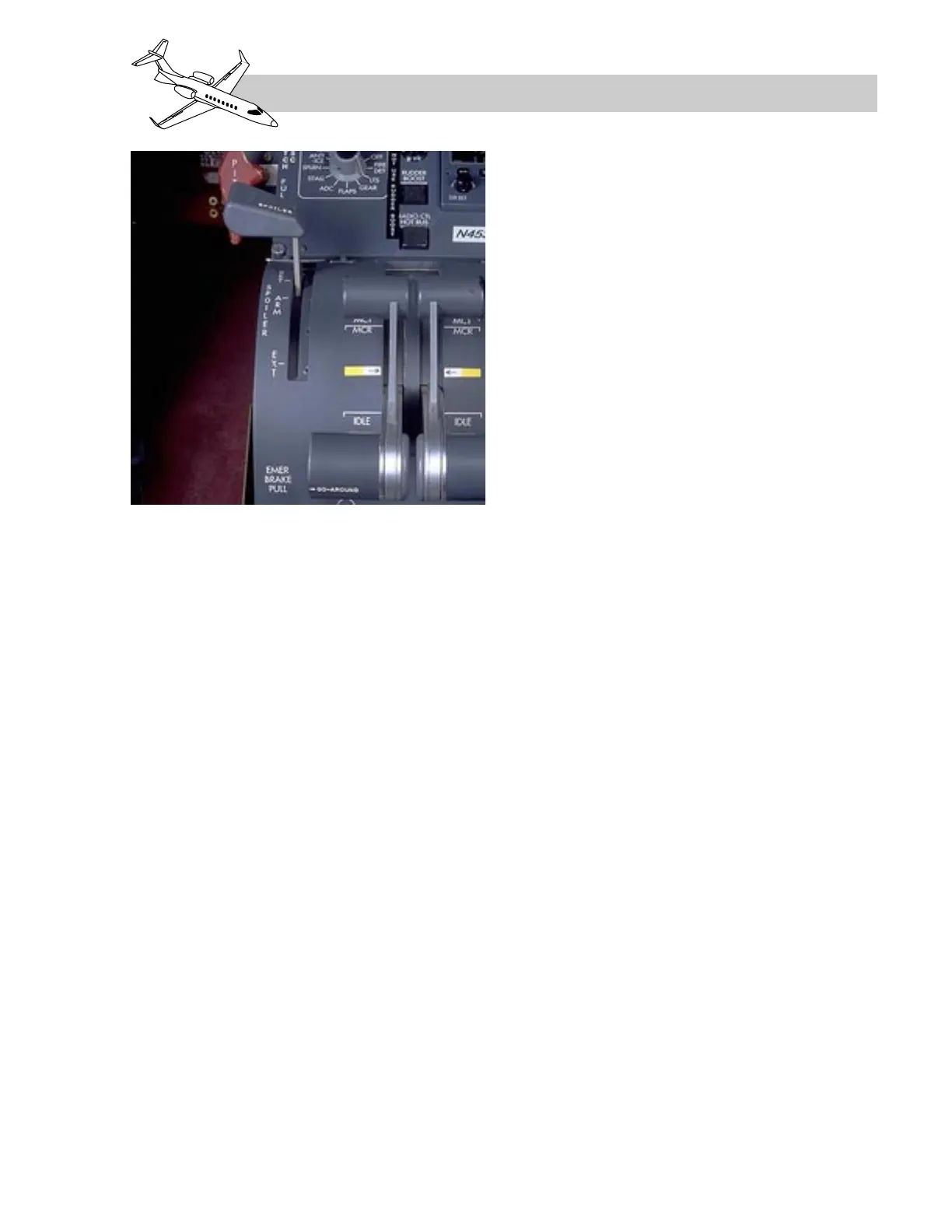
Spoiler Mode of Operation
The spoilers can be extended symmetrically
on the ground or inflight by moving the spoiler
lever aft of the ARM position. Placing the
lever to any position aft of ARM while on the
ground will cause full extension (60°) of the
spoilers. Spoiler extension on the ground re-
quires approximately 1 second and inflight, ap-
proximately 5 to 7 seconds.
When the spoiler lever is placed in any posi-
tion aft of ARM, the RVDTs attached to it
signal the spoileron computer. The computer,
in turn, energizes torque motors on the servo
valves to meter hydraulic pressure to the ex-
tend side of the actuators (Figure 15-21). The
computer receives spoiler extension feed-back
from the RVDTs attached to hinge points on
the spoilers, and it neutralizes the servo valves
when the spoilers reach the selected position.
Inflight, the amount of spoiler extension will
depend on the spoiler lever position and air-
speed. At high airspeeds the actuators cannot
extend the spoilers fully; therefore, spoileron
computer commands to the actuator servos
are limited by airspeed inputs from the ADCs.
At speeds below 175 knots, spoilers should ex-
tend to 60° when the spoiler lever is placed to
EXT, but at higher speeds full extension will
not be achieved.
When spoilers are extended or retracted in-
flight, the configuration trim system auto-
matically applies the appropriate amount of
pitch trim to compensate for the pitching mo-
ment caused by spoiler repositioning.
15-27
FOR TRAINING PURPOSES ONLY
LEARJET 45 PILOT TRAINING MANUAL
FlightSafety
international
Figure 15-22. Spoiler Lever