fails, the CAS will present a "DU 1, 2, 3 or 4
FAN FAIL" message (Table 16-2). Also, if
the temperature of the DU sub-assemblies
reaches approximately 120° C, the CAS will
present a "DU 1, 2, 3 or 4 OVHT" message
(Table 16-2).
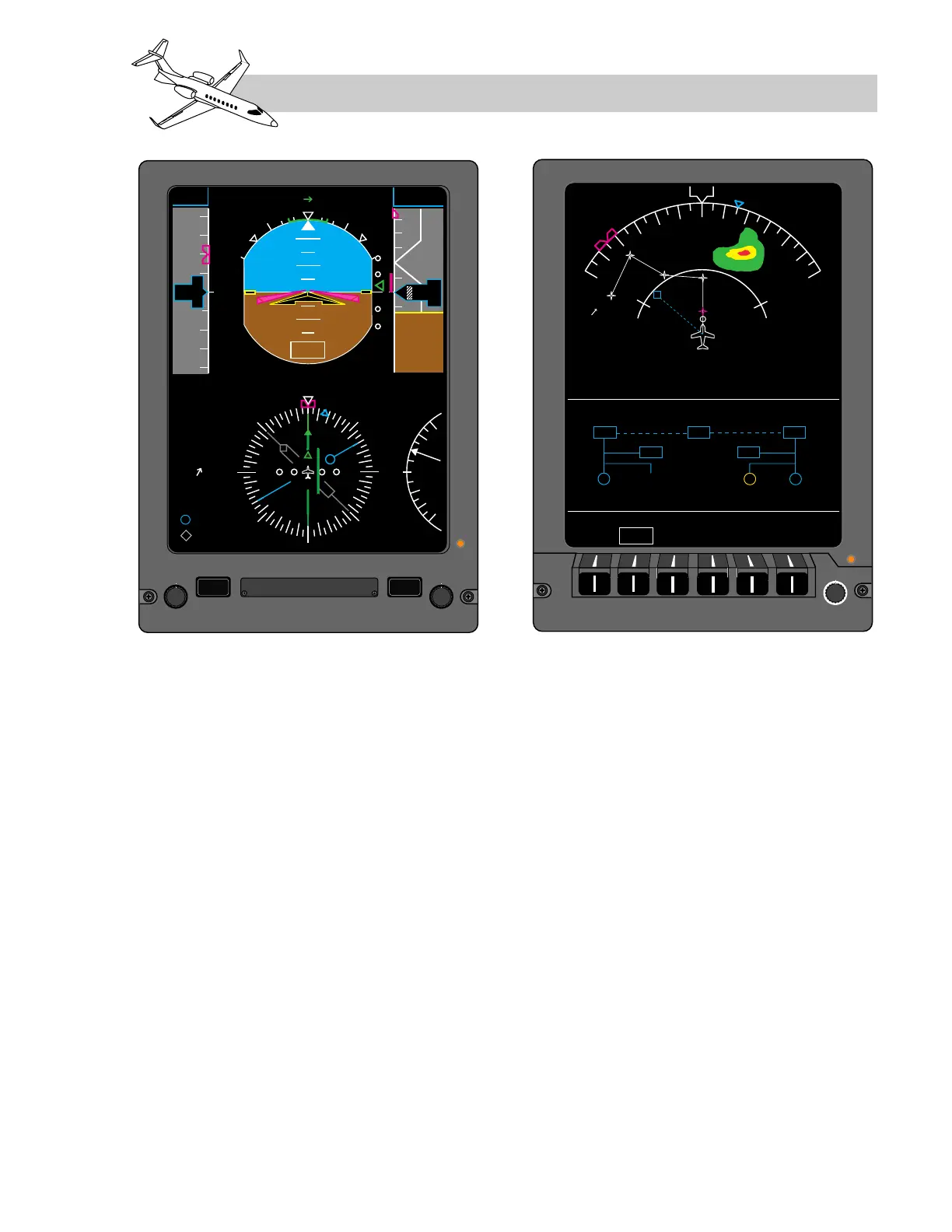
As illustrated in Figure 16-2, the two outboard
DUs function as the pilot and copilot's pri-
mary flight display (PFD). Normally, the pi-
lot's inboard DU is used to display EICAS
information, and the copilot's inboard DU is
used for the multi-function display (MFD);
however, EICAS, PFD, or MFD formats can be
displayed on the inboard DUs.
BEZEL CONTROLLERS
Each DU is equipped with a bezel controller
which consists of pushbuttons and knobs
(Figure 16-25). The PFD bezel controllers
(DUs 1 and 4) provide for selection of radio
altitude (RA) and barometric altitude (BARO)
minimums, and barometric corrections. The
outboard DUs also have slip/skid indicators
mounted above them, they are not located on
the bezels. The bezel controller on the two
inboard DUs (DU2 and DU3) consist of push-
buttons that access an array of menus, and
signal output circuitry to the display controller
for rotary knob control.
PFD Bezel Controller
As illustrated in Figure 16-26, the PFD bezel
controller is attached to the front of the dis-
play units, at the bottom. It performs the fol-
lowing functions:
• RA/BARO – This pushbutton allows the
minimums knob to be used to set values
for either RA or BARO. The digital read-
LEARJET 45 PILOT TRAINING MANUAL
16-37
FOR TRAINING PURPOSES ONLY
FlightSafety
international