System Installation
432-0012-00-12 Version 110 July 2016 12
Mounting Upright
The cable connectors terminating the pigtail cables on the camera are waterproof, vibration
tolerant, twist pin connectors designed for the marine environment. Appropriate sealing steps are
needed when making connections to on-board systems.
Caution: If you print the template from the PDF file, ensure that it is printed to the correct scale by
checking the dimensions prior to cutting any holes.
Using the template as a guide, mark the location of the holes for mounting the camera
Once the holes are drilled in the mounting surface, thread the power supply, video, and Ethernet
cables from the camera through the center hole, and then place the camera on the mounting
surface so the mounting bolts extend through the drilled holes. Secure and seal the camera body
to the mounting surface.
Mounting Upside Down
When a camera is going to be mounted upside down (ball down), a menu setting is used to
configure the system for ball down operation. Set the camera orientation after the camera the
camera is installed. Refer to “Configure Ball Down Installation” on page 34.
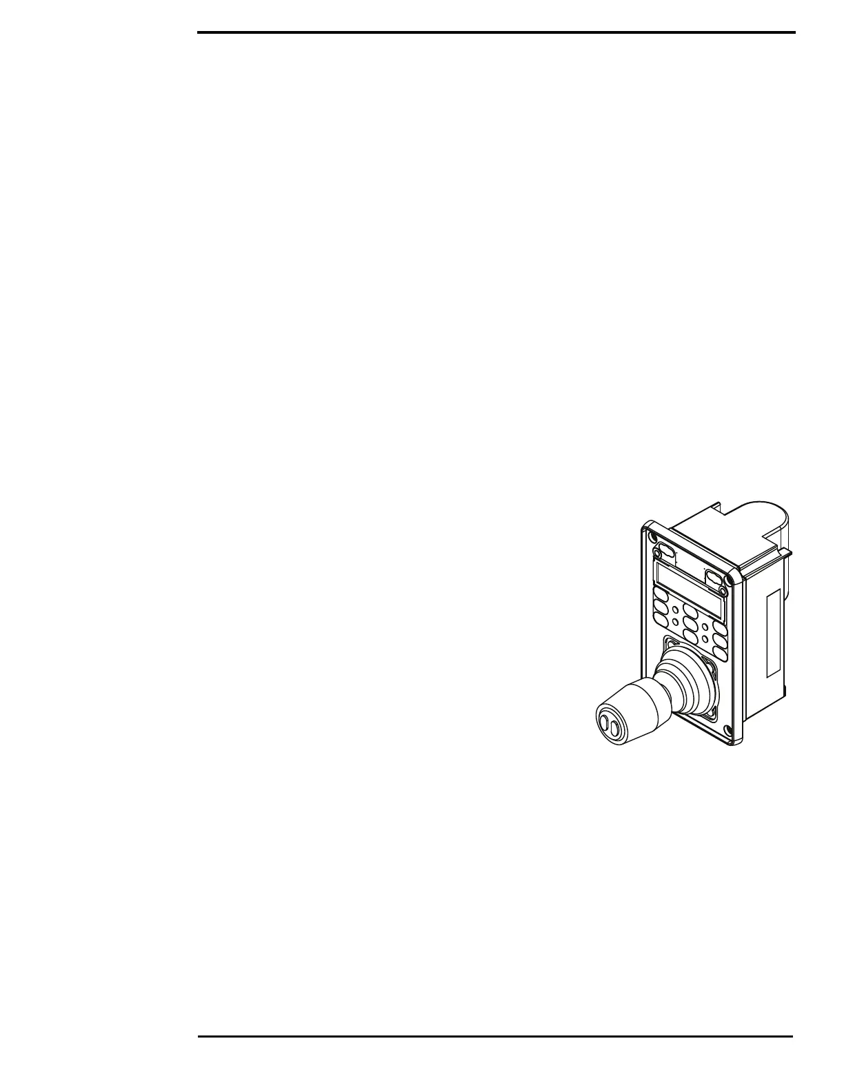
Installing the Joystick Control Unit (JCU II)
Mount the JCU II in an area that is close to the monitor being
used to display the M400 video output. Make sure the area you
choose leaves enough room for the cable under the JCU II. The
magnetic compass safe distance from the JCU II is 55 cm (21.7
in).
The JCU II can be mounted to the dash in any orientation, using
four captive mounting screws that hold panel mounting clamps.
When the mounting screws are tightened, the panel mounting
clamps rotate and extend away from the JCU II at a right angle,
and come into contact with the mounting surface. The JCU II
can be mounted to dash thicknesses ranging from 0.16 cm to
4.45 cm (0.063 in to 1.750 in). A trim bezel snaps on top of the
JCU II to cover the mounting screws. See “Installing the
Joystick Control Unit (JCU II)” on page 12 for detailed
instructions.
 Loading...