Electrical Connections
432-0012-00-12 Version 110 July 2016 15
Electrical Connections
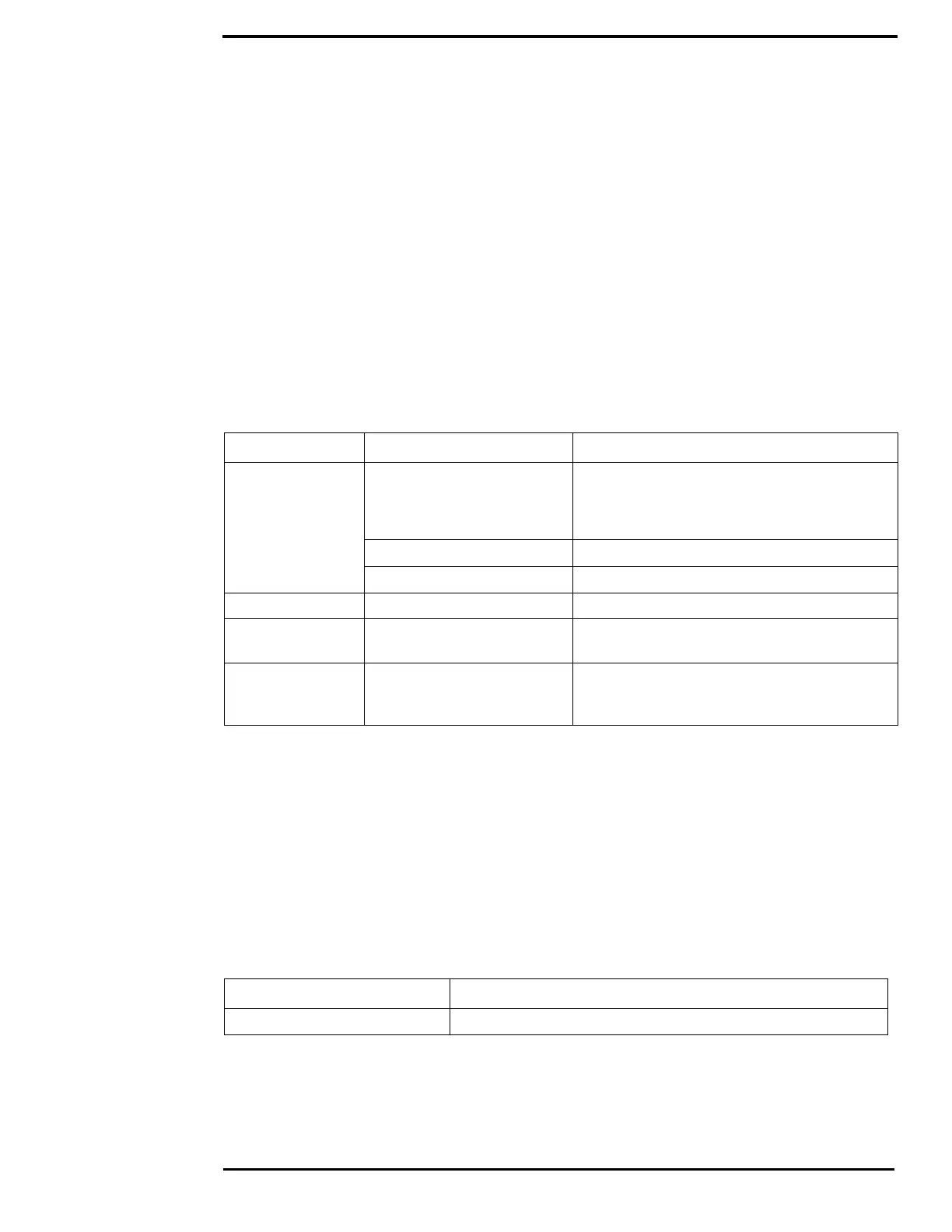
Watertight connectors/enclosures should be used on each of the electrical connections. Table 1.2
describes the connections for the cables attached to the camera.
Warning: Ensure power is removed before accessing power wires during installation or removal of
system components. Damage to equipment or injury to personnel may result.
Caution: During installation, ensure the cables exiting the bottom of the camera are not in contact
with sharp edges, do not bend at sharp angles, and are not pinched between the bottom of the
camera and the mounting surface. Do not pull on the cables with excessive force.
Caution: It is recommended that any built-up triboelectric charge on the Ethernet cable should be
discharged before connecting it to the JCU II and camera. This can be accomplished simply by
pressing an ungloved finger across the Ethernet RJ45 connector of the cable for a few seconds.
Connecting Power
The camera itself does not have an on/off switch. Generally the camera will be connected to a
circuit breaker and the circuit breaker will be used to apply or remove power to the camera. When
power is supplied, the camera will be in one of three modes: Booting Up, Standby, Parked, or
Powered On. The M400 Operator’s Manual has detailed information about powering and operating
the camera.
Installation of a circuit breaker (or fuse) in line with the power connection is required to protect the
power wiring and camera from power surge or short circuit.
The installer must use power cable wires that are sufficient size gauge or diameter for the supply
voltage and total load (camera and length of cable run), to ensure proper supply voltage at the
camera and adequate current carrying capacity.
TABLE 1.2 Connections Quick Reference
Cable Label Connectors Comment
Power Red Nominal 24 Vdc
Absolute range 12 Vdc to 32 Vdc
2.5 A typical, 5.5 A max maximum @ 24 Vdc;
5 A typical, 11 A max maximum @ 12 Vdc
Black Vdc return
Drain Chassis ground
HD/SDI BNC style Coax Digital video with isolation
Analog Video and
serial cable
F-type style Coax and pigtail
for serial (NMEA/factory test)
Analog video
Ethernet RJ45 Use shielded Ethernet cable for connection to
PoE switch providing power to JCU II and
optional connection to shipboard network.
TABLE 1.3 Fuse Recommendation
Model Fuse
M400 12 amp, slow blow at lowest voltage range (12 Vdc)

 Loading...