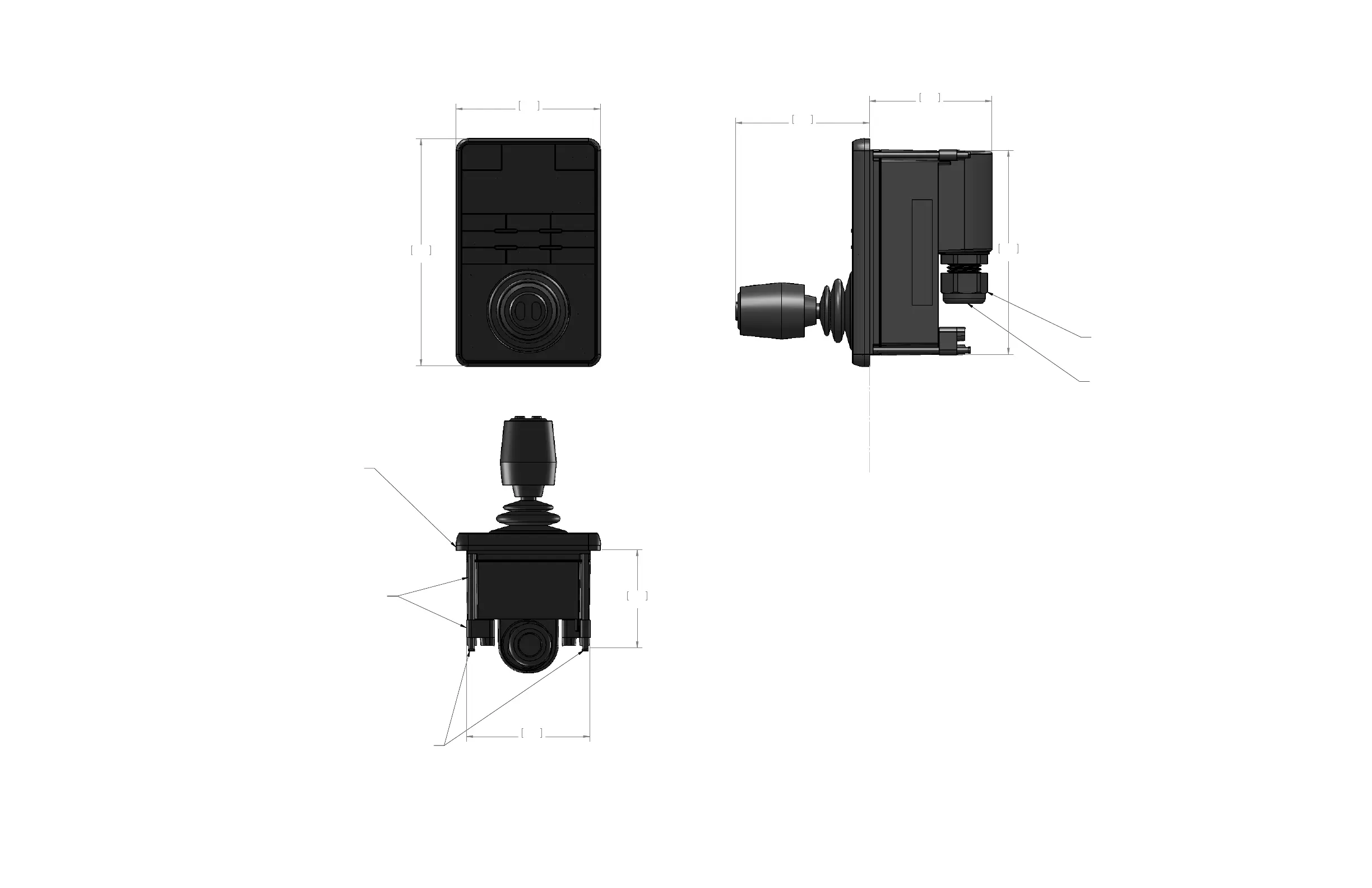
3.58
90.8
5.62
142.8
3.03
77.0
3.32
84.2
5.06
128.5
WITH CABLE INSTALLED, TURN NUT
1/4 TURN BEYOND HAND TIGHT.
GLAND SEAL DESIGNED FOR USE WITH DOUBLE
SHIELDED CAT 5 ETHERNET CABLE. USE OF SINGL
SHIELDED CABLE MAY REQUITE THE USE OF
ADDITIONAL SEALENT SUCH AS SILICON OR RTV
TO ENSURE SEALING OF ENCLOSURE
INSERT NETWORK CABLE RJ45 THROUGH GLAND
NUT AND SEAL BEFORE INSTALLING
IP66 RATED ABOVE GASKET. IP64 RATED BEHIND GASKET.
3.05
77.5
2.43
61.8
APPLY ADHESIVE SIDE OF GASKET TO JCU BODY.
MOUNTING PANEL THICKNESS RANGE 1.6-45 [0.036-1.750].
WHEN MOUNTING TO PANEL LESS THAN 6.3 [0.25] REVERSE PADDLES.
DURING INITIAL TIGHTENING, ENSURE MOUNTING
TABS ON SCREWS SWING FREE OF REAR OUSING.
WITH TABS RUN UP AGAINST REAR OF INSTRUMENT
PANEL, TIGHTNE 1/4 - 1/2 TURN BEYOND HAND TIGHT.
 Loading...