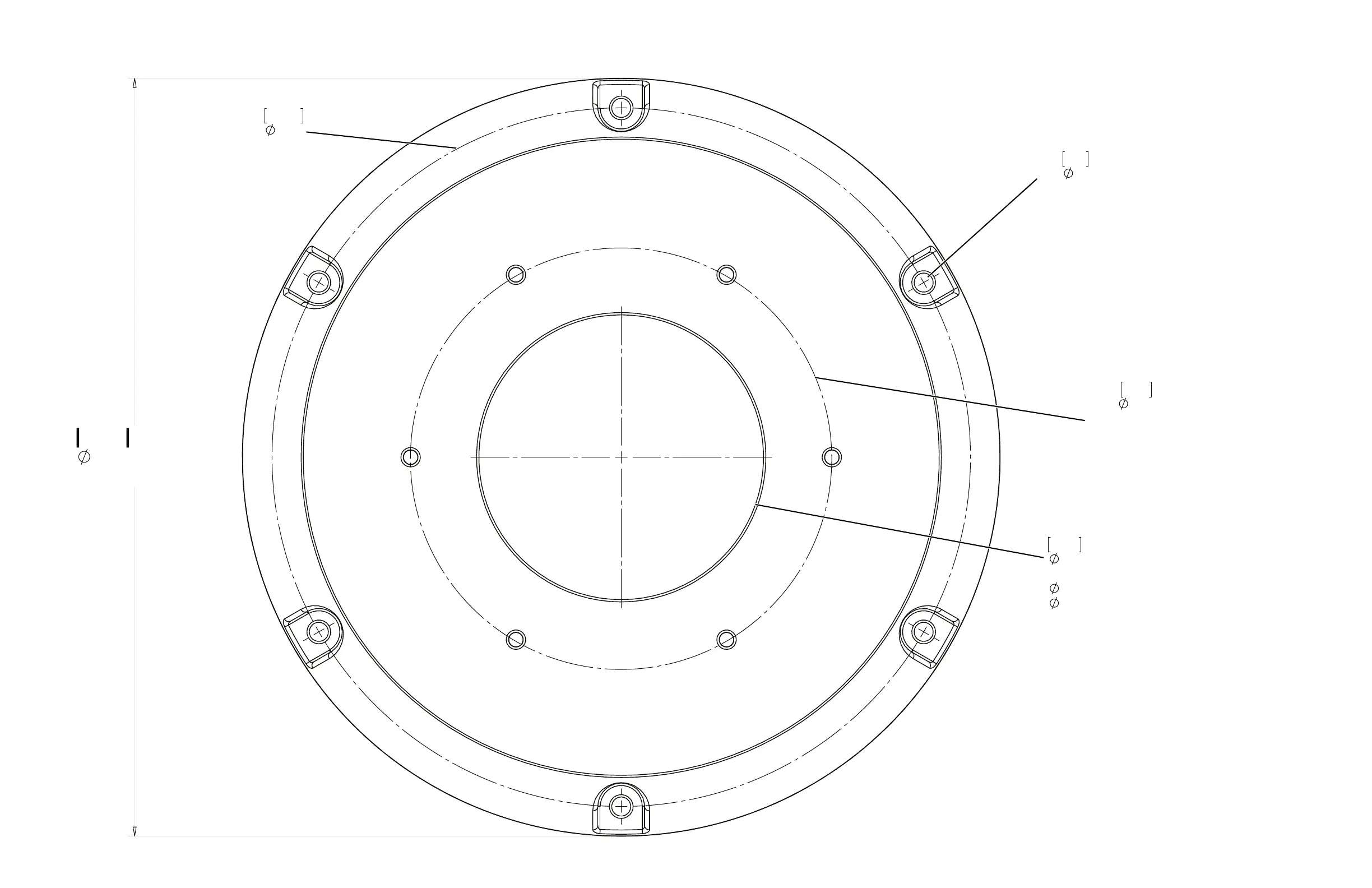
EasyManuals Logo

FLIR M400 Installation Guide

FLIR M400
59 pages
To Next Page IconTo Next Page
To Previous Page IconTo Previous Page
Page #58 background imageLoading...
Page #58 background image
M400 Installation Guide
432-0012-00-12, version 110 July 2016 58
Appendix 1
Appendix 1
12.75
323.9
Top Down Riser OD
6X
.32
8.2
Riser Clearance Holes
Recommend:
M8 socket head cap screws, or
5/16" - 18 socket head cap screws, or
5/16" - 18 hex head sheet metal screws
Type and length dependant on mounting surface
316 stainless steel
Apply thread locker (Loctite 262 or equivalent)
4.79
121.6 Riser cable clearance hole
Recommended deck port:
30.0 [1.18] min
130.0 [5.12] max
NOT TO SCALE
11.75
298.5
Top down riser bolt circle
7.09
180.0
Base cup hole circle
M400 Riser Installation Document Sheet 1

Other manuals for FLIR M400

Questions and Answers:

Question and Answer IconNeed help?

Do you have a question about the FLIR M400 and is the answer not in the manual?

FLIR M400 Specifications

General IconGeneral
Thermal Resolution640 x 480
Image StabilizationYes
Spectral Range7.5 - 13.5 µm
Frame Rate30 Hz
Power Supply24 VDC
Digital Zoom8x
Pan/Tilt360° continuous pan, ±90° tilt
Video OutputHD-SDI
EnvironmentalIP66
Sensor TypeVOx Microbolometer
Thermal Sensitivity<50 mK
Temperature Range+55°C (–13°F to +131°F)
Operating Temperature-25°C to +55°C (-13°F to +131°F)

Related product manuals