427-0014-00-10 Revision 210 Copyright © 2008 FLIR Systems, Inc. 5
TABLE OF FIGURES
Figure 1-1: Thermal image from SR-Series camera .....................................................................6
Figure 2-1 : Daylight camera on left; Thermal image on right.......................................................8
Figure 2-2: White Hot palette on left, Black Hot palette on right .................................................10
Figure 2-3: SR-35 Camera with and without the Environmental Enclosure................................10
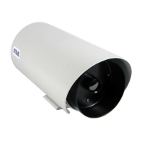
Figure 2-4: SR-100P with Sun Shroud........................................................................................11
Figure 3-1: Rear view of SR-Series camera ...............................................................................12
Figure 3-2: Earth Ground Connection.........................................................................................13
Figure 3-3: Serial Communications Options ...............................................................................15
Figure 4-1: SR-100 Connection Terminal ...................................................................................17
Figure 4-2: Screw Terminal Connector .......................................................................................18
Figure 5-1: SR-100P with Sun Shroud........................................................................................19
Figure 5-2: Mating connector as seen from end of cable............................................................20
Figure 5-3: SR-100P Enclosure Rear .........................................................................................21
Figure 6-1: Front view of SR-Series camera...............................................................................22
Figure 6-2: Serial Communications DIP Switches ......................................................................23
Figure 6-3: SR-Series Connections (VSR-6, SR-19, SR-35, and SR-50)...................................24
Figure 6-4: Tongue and Groove Alignment.................................................................................25
Figure 7-1: Backlit daylight camera on left; thermal image on right ............................................26
Figure 9-1: Camera Side View....................................................................................................33
Figure 9-2: Camera Rear View ...................................................................................................33
Figure 9-3: Enclosure Mounting Foot (all cameras except for SR-100P) ...................................34
Figure 9-4. SR-100P Dimensions without Sun Shroud..............................................................35
Figure 9-5. SR-100P Length with Sun Shroud............................................................................35
Figure 9-6 . SR-100P Width and Height with Sun Shroud ..........................................................36