5700A/5720A Series II Calibrator
Service Manual
3-36
3-24. AC Current Test, 2 mA and 200
µ
A Ranges
The equipment required for the alternating current accuracy verification test for the 2 mA
and 200 µA ranges is listed in Table 3-10. Use Table 3-28 (5720A) or 3-29 (5700A0 for
the test record.
Table 3-10. Equipment Required for Alternating Current Accuracy Test for the 2 mA and 200 µA
Ranges
Equipment Model or Description
AC Measurement Standard Fluke 5790A
Metal Film Resistor 200Ω, 1/8w, ±1%, T9 (P/N 309724) mounted on a dual banana plug.
Metal Film Resistor 2 kΩ, 1/8w, ±1%, T9 (PN 335422) mounted on a dual banana plug
Cable Pomona 1368-A-18. Double banana to single banana plugs.
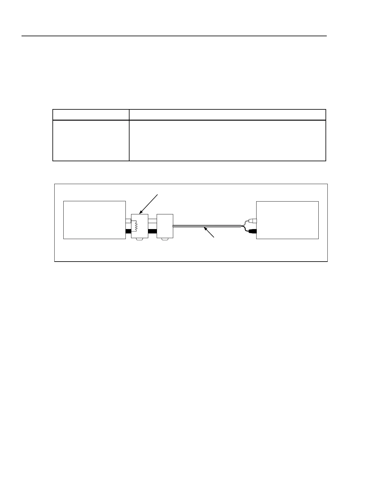
1. Connect the equipment as shown in Figure 3-13.
Hi
Calibrator (UUT)
Output
Pomona Cable
1362-A-18
Lo
Metal Film Resistor
Mounted on Dual
Banana Plug
5790A
Input 2
Hi
Lo
200
Ω
F3-9.EPS
Figure 3-13. Alternating Current Test Setup 2 mA and 200 µA
Note
An explanation of the rationale for using metal film resistors to measure
ac current follows this procedure.
2. Set the Calibrator for precisely +2 mA dc using the correction from previously
recorded data, i.e. set the Calibrator error display to the value recorded for +2 mA dc
(Table 3-9 or 3-11).
3. When the 5790A settles on a reading, push the SET REF soft key on the 5790A.
4. Set the Calibrator for precisely -2 mA dc output using the correction from previously
recorded data, i.e., set the Calibrator error display to the value recorded for -2 mA dc,
in Table 3-10.
5. Press the AVG REF soft key on the 5790A after the 5790A reading settles.
6. Set the Calibrator to 2 mA at 10 Hz and OPERATE.
7. Record the error displayed on the 5790A in Table 3-28 or 3-29, and verify results are
within spec.
8. Return to the error corrected +2 mA DC output that was set in step 2. Verify that the
5790A display returns to a zero reading ±10 PPM. If necessary, repeat steps 2
through 6 until the required results are obtained.