EasyManuals Logo

Fluke 5700A Series User Manual

Fluke 5700A Series
576 pages
To Next Page IconTo Next Page
To Previous Page IconTo Previous Page
Page #214 background imageLoading...
Page #214 background image
5700A/5720A Series II Calibrator
Service Manual
3-4
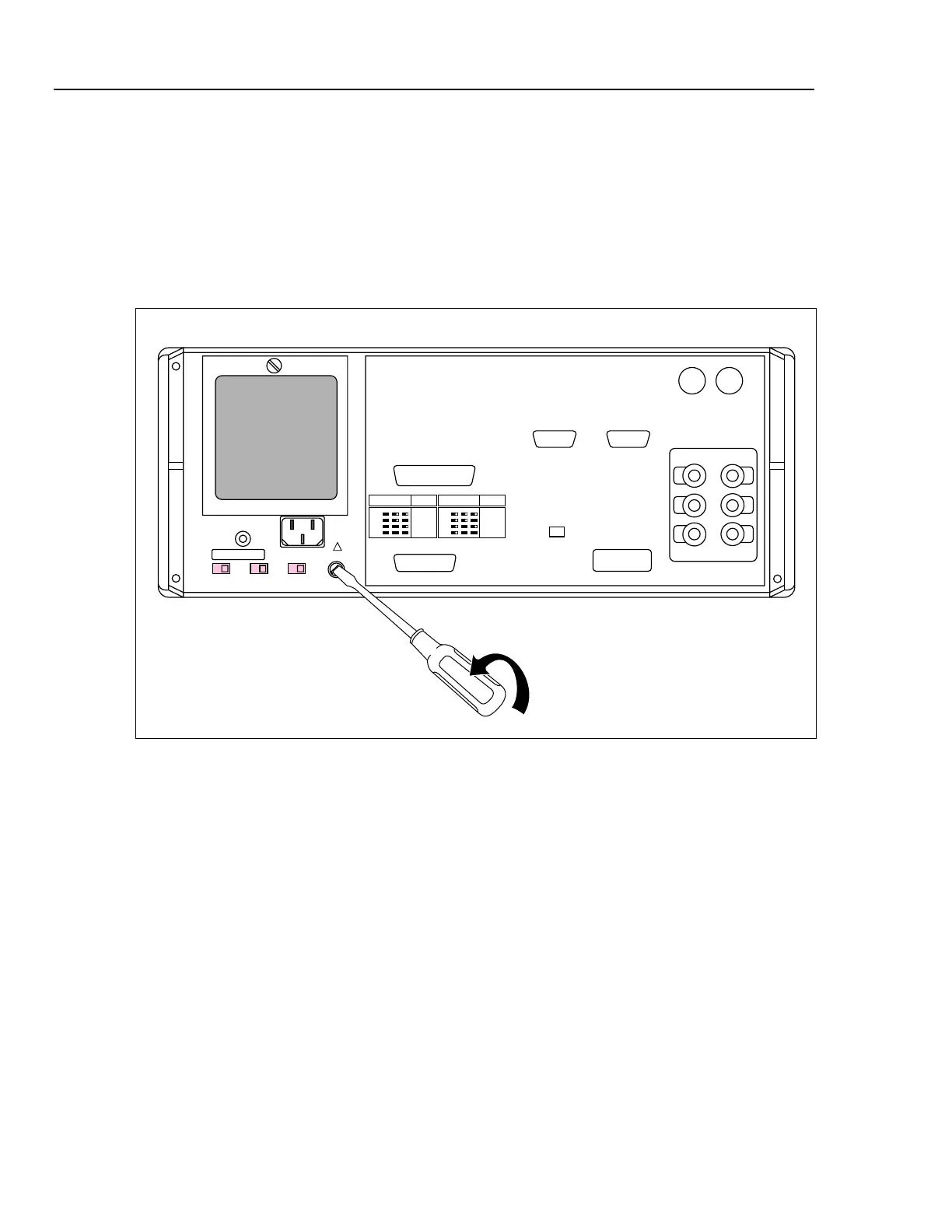
3-2. Accessing the Fuse
The fuse is accessible from the rear panel. The fuse rating label to the right of the fuse
holder shows the correct replacement fuse ratings for each operating voltage. To access
the fuse, refer to Figure 3-1 and proceed as follows:
1. Disconnect line power.
2. Using a standard screwdriver, turn the fuse holder counterclockwise until the cap and
fuse are disengaged.
VOLTAGE
SELECTION
FUSE-F1
T 3A
250V
(SB)
100V
S2 S3 S4
110V
115V
120V
VOLTAGE
SELECTION
FUSE-F1
T 1.5A
250V
(SB)
200V
S2 S3 S4
220V
230V
240V
CHASSIS
GROUND
S2 S3 S4
FUSE -F1
!
F7-1.EPS
Figure 3-1. Accessing the Fuse

Table of Contents

Questions and Answers:

Question and Answer IconNeed help?

Do you have a question about the Fluke 5700A Series and is the answer not in the manual?

Fluke 5700A Series Specifications

General IconGeneral
TypeMultifunction Calibrator
Operating Temperature0°C to 50°C
Storage Temperature-40°C to 70°C
Humidity10% to 90% non-condensing
Frequency Range10 Hz to 1 MHz
AccuracyVaries by function and range. See manufacturer's specifications for details.
Output StabilityVaries by function and range. See manufacturer's specifications for details.
Power Requirements50 Hz to 60 Hz

Related product manuals