Calibration and Verification
Full Verification 3
3-35
Note
When verifying the 5725A Amplifier at the 10A level, allow sufficient time
for the A40A-10 shunt to reach thermal stability after initially applying the
current.
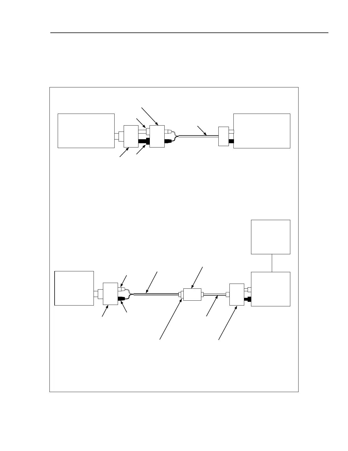
A. Alternating Current Test Setup, 22 mA to 2A Using 5790A Input 1
Hi
5790A
Input 1
Pomona Cable
1368-A-18
Lo
Red
Black
792A-7004
A40 Current Shunt Adapter
A40 Current Shunt
B. Alternating Current Test Setup, 10A Using 5790A Input 1
Hi
5790A
Input 1
FLUKE A45-4003
P/N 212852
Cable
Lo
Red
Black
792A-7004
A40 Current
Shunt Adapter
Calibrator (UUT)
5725A (UUT)
Calibrator (UUT)
Pomona Cable
5268-C-12
A40A 10A
Current Shunt
Pomona Model 1707
UHF(F) to Banana
Adapter
UHF(M) to BNC(F)
Adapter
Kings KC-99-34
F3-8A.EPS
Figure 3-12. Alternating Current Test Setup