Troubleshooting
Component-level Troubleshooting 5
5-59
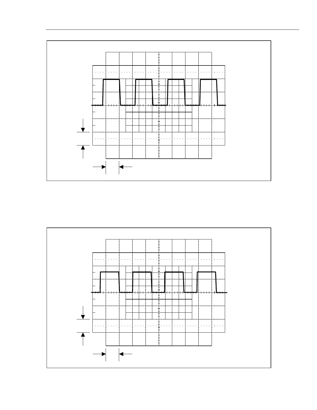
1 V
10 ms
F5-19.EPS
Figure 5-19. Waveform at TP4, Calibrator Set to 6.5V
5. Check CH2 FILTER INPUT. Connect an oscilloscope probe to TP7 (common to
TP3). Set the Calibrator to 6.5V dc, operate. Set the oscilloscope to 2V/div at 2
ms/div. Verify the oscilloscope displays pulses similar to those shown in Figure 5-20.
1 V
10 ms
F5-20.EPS
Figure 5-20. Waveform at TP7