Theory of Operation
Analog Section Detailed Circuit Description 2
2-41
U5 with heat sink, bypass capacitors C10 and C28, and protection diodes CR9, CR10,
and CR12. Resistors R4 and R8 set the output voltage in the same manner as the +44S
supply. Capacitor C12 improves ripple rejection. Diodes CR9 and CR10 protect U5
against input shorts, while CR12 protects against reverse voltage.
2-77. Guarded Digital Control Circuitry
The Inguard CPU controls all the analog assemblies. It communicates with the
Unguarded CPU assembly (A20) through a serial fiber-optic link. The Inguard CPU is a
Hitachi 637A01Y0 CMOS microcontroller (U56) with 16K x 8 bit (16 KB, or 16
kilobyte) internal CMOS EPROM. Support circuitry includes 8K x 8 bits (8 KB) of
external CMOS static RAM, watchdog timer circuitry, reset and power glitch detect
circuitry, test switches, a serial fiber-optic link to the unguarded CPU, and decoders and
buffers to interface to the guarded digital bus. The assembly also generates an 8 MHz
sine wave for use by some of the analog assemblies.
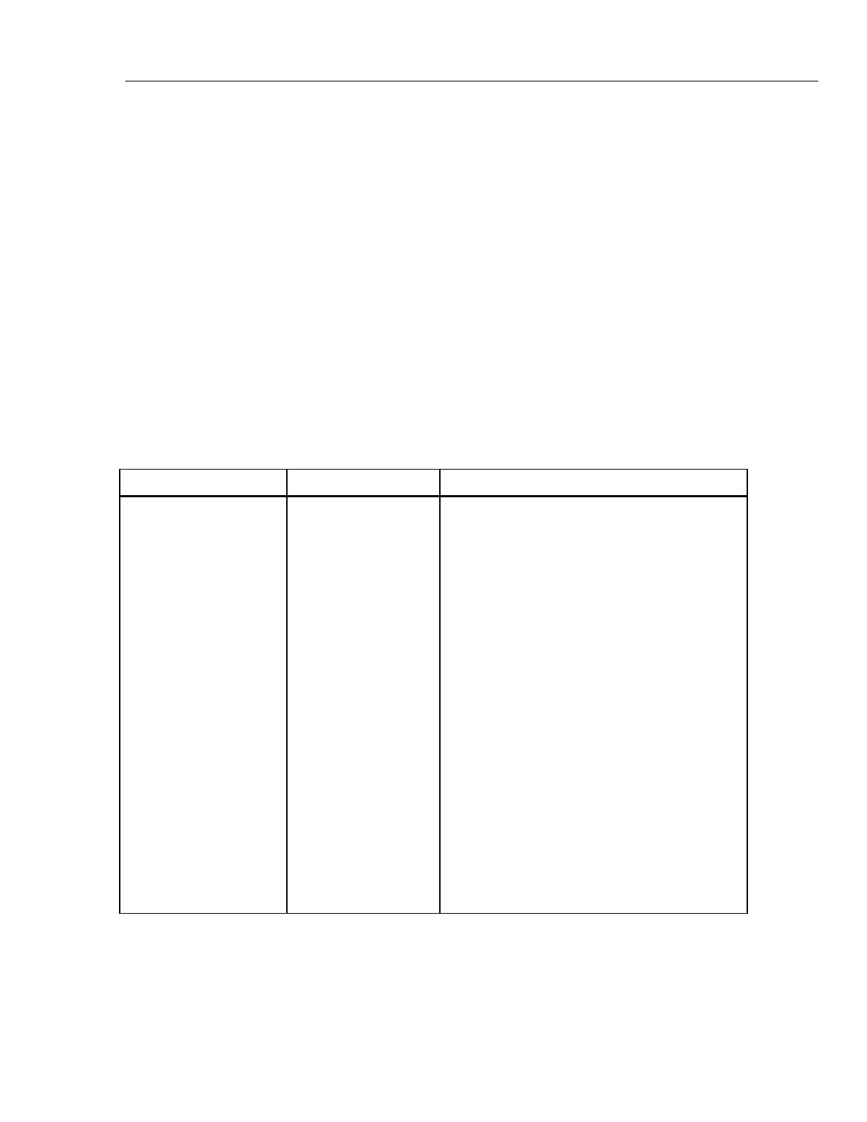
2-78. Inguard CPU Memory Map
Table 2-11 shows the memory map of the Inguard processor.
Table 2-11. Inguard CPU Memory Map
Address Space (Hex) Name Use
0000 - 0027 Internal Registers on the 6301
0028 - 003F Unused memory space
0040 - 013F Internal RAM 256 Bytes
0140 - 3FFF CS0* Unused memory space
4000 - 4007 CS1* Wideband Output (A5)
4008 - 400F CS2* Current/Hi-Res (A7)
4010 - 4017 CS3* Switch Matrix (A8)
4018 - 401F CS4* Ohms Cal (A9)
4020 - 4027 CS5* Unused
4028 - 402F CS6 DAC (A11)
4030 - 4037 CS7* DAC (A11)
4038 - 403F CS8* Current/Hi-Res (A7)
4040 - 4047 CS9* Oscillator Control (A12)
4048 - 404F CS10* Oscillator Output (A13)
4050 - 4057 CS11* High Voltage Control (A14)
4058 - 405F CS12* Power Amplifier (A16)
4060 - 4067 CS13* Rear Panel (A21) Boost
4068 - 406F CS14* Current/Hi-Res (A7)
4070 - 4077 CS15* Wideband Oscillator (A6) Unused
4078 - 407F Unused
4080 - 5FFF Unused(memory overlay of 4000-407F)
6000 - 9FFF Unused
A000 - BFFF External RAM
C000 - FFFF Internal ROM or EPROM
2-79. Inguard Memory Configuration
The microcontroller (U56) has 16 KB (kilobytes) of internal EPROM program memory.
IC U62 provides 8 KB of external static CMOS RAM, with a jumper option for a plug-in
replacement with a 2 KB device.