Theory of Operation
Analog Section Detailed Circuit Description 2
2-33
2-56. Analog Section Detailed Circuit Description
Detailed descriptions of each assembly in the analog section are provided here.
Simplified schematics are provided to supplement the text.
2-57. Filter/PA Supply (A18), Low-voltage Filter/Regulator Section
The Filter assembly receives various ac inputs from the main power transformer and
provides unregulated dc to the Regulator/Guard Crossing assembly (A17), and regulated
dc supplies +5FR1, -18FR1, and -5FR2 to the DAC assembly. The unregulated supplies
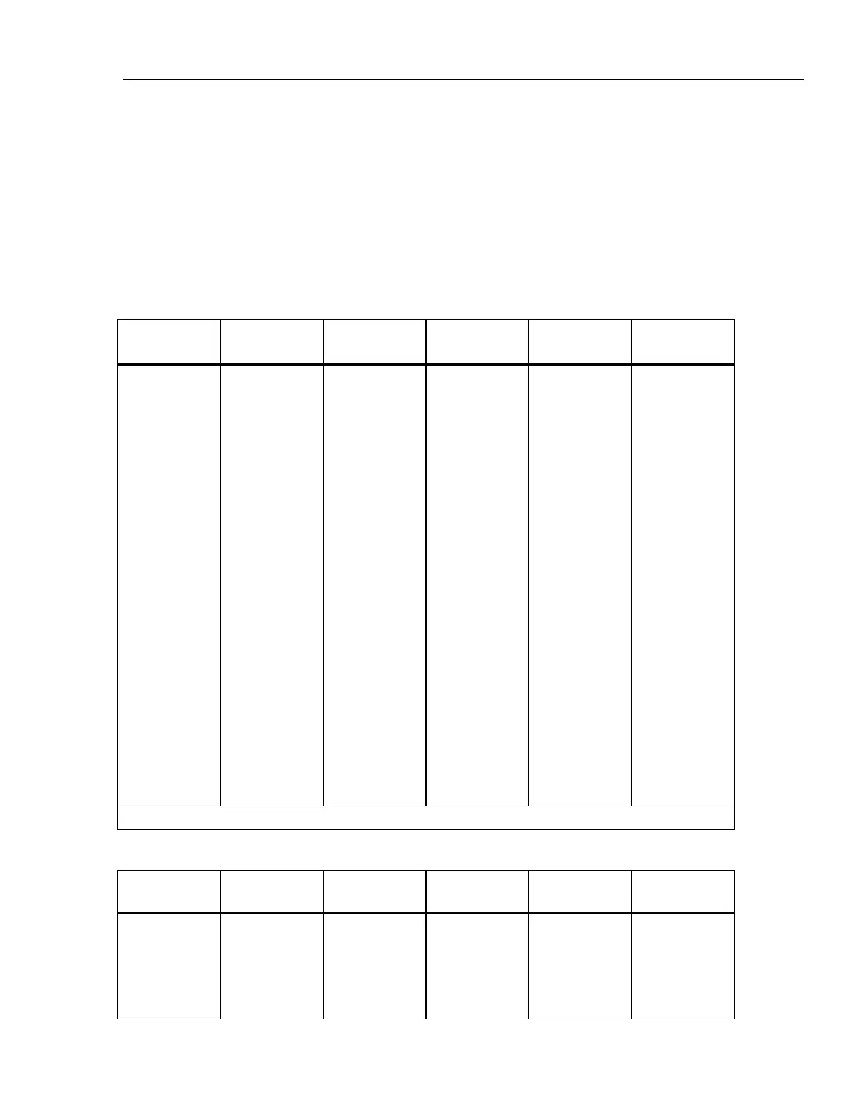
are listed in Table 2-8 and the regulated supplies are listed in Table 2-9.
Table 2-8. Unregulated Supplies from the Filter Assembly
Signal Name
Nominal
Output
Tolerance
Max. P-P
Ripple
Rated Output
Test
Point
+15 OSCR 27V +/-8V 2V 200 mA TP2
-15 OSCR 27V +/-8V 2V 200 mA TP5
OSC COM RETURN TP4
+5 LHR 12V +/-4V 3V 3.5A TP1
-5 LHR 12V +/-4V 2V 400 mA TP6
LH COM RETURN TP3
+44 SR 60V +/-15V 3V 155 mA TP7
-44 SR 60V +/-15V 3V 460 mA TP9
44 S COM* TP22
+17 SR 27V +/-8V 3V 1.3A TP10
-17 SR 27V +/-8V 3V 1.3A TP14
17 S COM* RETURN TP12
+5 FR1R 12V +/-4V 2V 400 mA TP17
-18 FR1R 27V +/-8V 2V 50 mA TP20
FR1 COM RETURN TP19
+30 FR1R 50V +/-15V 3V 85 mA TP15
FR1R COM RETURN TP16
+30 FR2R RETURN +/-15V 3V 85 mA TP8
FR2 COM TP11
* 44 S COM and 17 S COM are tied together on the Regulator/Guard Crossing assembly (A17).
Table 2-9. Regulated Supplies from the Filter/PA Supply
Signal Name
Nominal
Output
Tolerance Current Limit Rated Output Test Point
-5 FR2 -5V +/-0.3V 0.15A 0.03A TP13
FR2 COM RETURN TP11
+5 FR1 +5V +/-0.3V 2A 0.1A TP18
-18 FR1 -18V +/-0.9V 2A 0.05A TP21
FR1 COM RETURN TP19