5700A/5720A Series II Calibrator
Service Manual
5-50
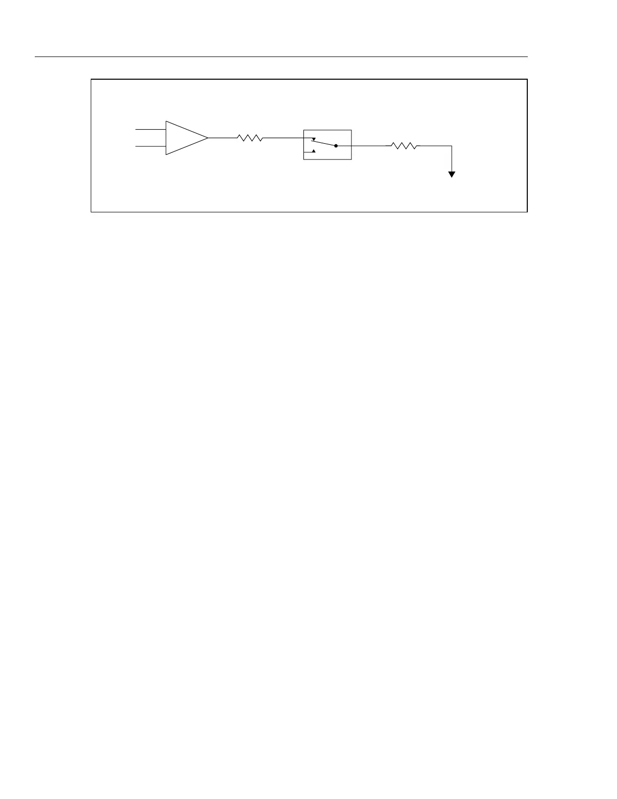
10 k
HR2
SHUNT
1.2
R14
2V ac
±10%
K9C, K8C,
K7A, K5D,
K10, K13
SCOM
Ω
Ω
F5-11.EPS
Figure 5-11. Verifying the 220 mA Range of the 22 mA/220 mA Amp Circuit
9. Check the POS. FB BUFFER. Set the Calibrator to 200 mA, standby. Set the external
ac reference to 4.6V at 1 kHz. Using a DMM measure the ac voltage at pin 5 of the
HR2 resistor network and Note the reading. Next, measure the voltage at TP4 and
verify it is the same as the previous Noted reading ±0.1%. If a failure is detected,
check U3, K5B, K6B, K8B, K9B, and the associated components.
10. Check the I-GUARD BUFFER. Set the Calibrator to 200 mA, standby. Set the
external ac reference to 4.6V at 1 kHz. Measure the ac voltage at TP4 with a DMM
and Note the reading. Next, measure the voltage at U4 pin 6 and verify it is the same
as the previous Noted reading ±0.01%. If a failure is detected, check U4 and its
associated components.
Note
Replace or reconnect jumper E1 and remove the external ac reference
from the Current/Hi-Res assembly before continuing.
11. Check the Input Switching. Set the Calibrator to 2 mA dc, operate. Using a DMM,
measure the dc voltage at TP1 (common to TP2) and verify it is 20V dc ±0.25%.
Next, set the Calibrator to ac 2 mA at 1 kHz operate and measure the ac voltage at
TP1 and verify it is 20V ac ±25%. If a failure is detected, check K1, Q20-Q23, and
their appropriate drive circuitry.
12. Check the Z1 resistor network. Set the Calibrator to 2 mA dc, operate. Using a DMM
measure the dc voltage at pins 8 and 3 of Z1 and verify they are 1.818V dc ±0.35%.
If a failure is detected, check Z1 and the HR2 hybrid.
13. Check the CURRENT/COMPLIANCE VOLTAGE MONITOR. Connect a 10Ω 1%
resistor across the Calibrator output and set the Calibrator to 200 mA at 1 kHz,
operate. Using a DMM measure the ac voltage at the OUT HI binding post and edit
the current output until it measures 2.0V ac ±0.01V. Next, measure the dc voltage at
TP9 and verify it is 0.238V dc ±10%. If a failure is detected, check U5, U6, and the
associated components in the CURRENT/COMPLIANCE VOLTAGE MONITOR
circuit.
14. Check the COMPLIANCE LIMITER. Connect a shorting jumper across the
Calibrator output and set the Calibrator to 2 mA dc, operate. Using a DMM monitor
the dc voltage at TP4. Remove the shorting jumper at the Calibrator output. The
voltage at TP4 should not exceed 11V ±5% before the Calibrator trips to standby. If a
failure is detected, check Q24, Q25, CR10, CR11, and the associated components in
the Compliance Limiter Circuit.