Calibration and Verification
Full Verification 3
3-31
5. Algebraically add column B to column A. Enter the result on the test record. Verify
that it is within the test limits shown.
6. Repeat steps 2 through 5 using the Fluke 742A Resistance Standards and Calibrator
output currents shown in Tables 3-25 or 3-26.
7. If the Calibrator is attached to a 5725A Amplifier, connect the Y5020 high-current
shunt to the 5725A output terminals. Connect the dc DMM to the Y5020 high-current
shunt voltage output connector.
8. Set the Calibrator to 10A, -10A, 5A, 3A and -3A and record the dc DMM readings
on the 5725A Amplifier dc current test record. Divide these readings by the certified
value of the Y5020 high current shunt, record the resultant current and verify that it is
within the test limit shown.
3-21. AC Voltage Frequency Accuracy Test
This test requires the use of a frequency counter. Philips model PM6669 is
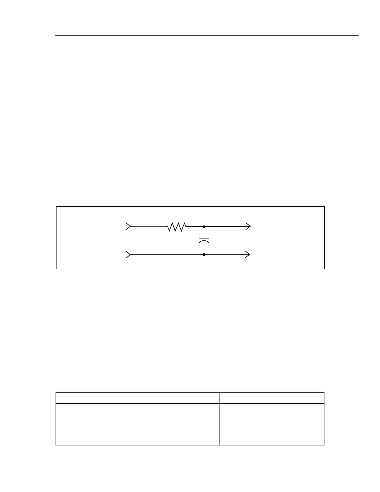
recommended. Use Table 3-22 for the test record. When using Philips Model PM 6666, it
is recommended to use a 1 MHz Low Pass Filter as shown in Figure 3-10. Refer to Table
3-15, Minimum Use Requirements, for substitution information.
1.59 kΩ Resister
Metal Film P/N 344341
Calibrator Main
Output Terminals
10 pF
Capacitor
P/N 713875
PM6666
Input A
Mount components on a duel banana adapter from ITT Pomona. Part Number 1837
F3-6A.EPS
Figure 3-10. 1 MHz Low Pass Filter
To check the Calibrator frequency accuracy, proceed as follows:
1. Connect the frequency counter to the output terminals of the Calibrator.
2. Set the Calibrator to 1V at the output frequencies listed in Table 3-22. Verify that the
counter reads within the limits shown on the test record.
3. Disconnect the counter from the Calibrator.
3-22. Output Level Tests For AC V Ranges
This test requires the use of equipment listed in Table 3-7.
Table 3-7. Equipment Required for AC V Output Level Tests
Equipment Model
AC Measurement Standard Fluke 5790A
BNC(F) to Dual-Banana Plug Adapter (2 required) Pomona 1269
Coax Cable - RG-58A/U or RG-58C/U with BNC(M)
Connectors, 12 ± 1 inch Long