Troubleshooting
Component-level Troubleshooting 5
5-51
5-8. Hi-Res Oscillator Section
Proceed as follows to troubleshoot the Hi-Res Oscillator Section of the Current/Hi-Res
assembly (A7):
1. Remove the four small shields (two on each side) and place the Current/Hi-Res
assembly on the analog reverse extender card. Power up the Calibrator.
Note
All measurements are referenced to LHCOM (TP18).
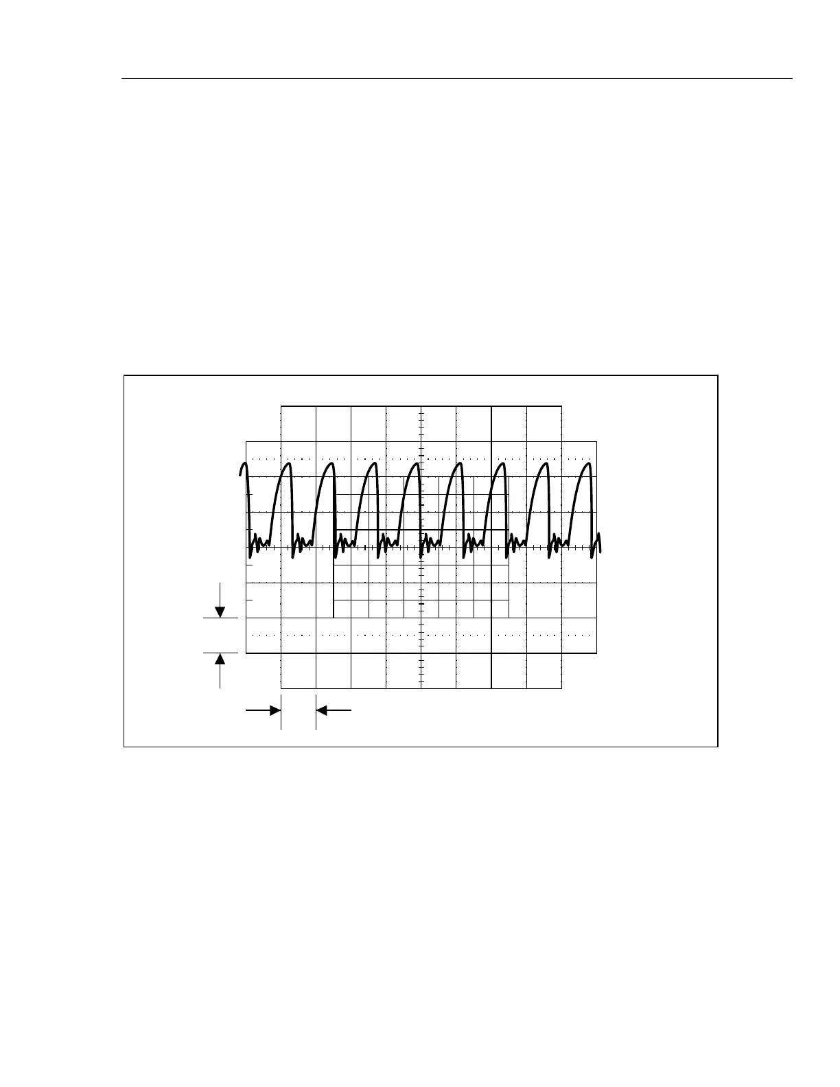
2. Check the 8 MHz reference. Set the Calibrator to 2V at 1 kHz, operate. Connect an
oscilloscope to U13 pin 4 and verify it displays a 8 Mhz signal similar to that shown
in Figure 5-12. If a failure is detected, first verify that control line HI-RES ON/OFF
is a logic low by measuring U15 pin 12. If not U7 is probably at fault. If this control
line is correct check U13 and its associated components.
1 V
10 ms
F5-12.EPS
Figure 5-12. Waveform at Pin 4 of U13
Note
The input CLK and CLK* is a low level (400 mV p-p) signal generated by
the Regulator/Guard Crossing assembly.
3. Check the 2 MHZ REF. Set the Calibrator to 2V at 1 kHz, operate. Connect an
oscilloscope to TP12 and verify it displays a 2 MHz signal similar to that shown in
Figure 5-13. If a failure is detected, check U14A and U14B.
4. Check the 6-12 MHZ signal. Set the Calibrator to 2V at 1 kHz, operate. Connect an
oscilloscope to TP13 and verify it displays a 10 Mhz signal similar to that shown in
Figure 5-14. Also measure the frequency of this signal using a frequency counter and
verify it is within 9.999 MHz to 10.001 MHz. If a failure is detected, with either test
continue on as follows. If the signal and frequency are correct, skip to step 9.