5700A/5720A Series II Calibrator
Service Manual
5-46
switches to a high(~+17V) level while all the others remain at a low (-11V) level. If a
failure is detected, check U8, U10, U11, and U13.
14. Check the Filters. Disconnect the cable between the Wideband Oscillator assembly
and Wideband Output assembly at J1 on the Wideband Output assembly. Set the
Calibrator to 1V at 1.2 MHz, 1.9 MHz, 2 MHz, 3.9 MHz, 4 MHz, 7.9 MHz, 8 MHz,
15.9 MHz, 16 MHz, and 30 Mhz. Connect an oscilloscope to TP14 and verify it
displays a distortion-free sine wave at each frequency. If a failure is detected, check
the corresponding Filter circuit.
Table 5-1. Verifying Multiplexer U66
5700A/5720A
Series II
Wideband Output
A
Pin 7
B
Pin 9
C
Pin 10
TP10
1-32 MHz
1.2 Mhz -5V -5V -5V 1.2 MHz
2.0 Mhz 0V -5V -5V 2.0 MHz
4.0 Mhz -5V 0V 0V 4.0 MHz
8.0 Mhz -5V -5V 0V 8.0 MHz
16.0 Mhz 0V 0V -5V 16.0 MHz
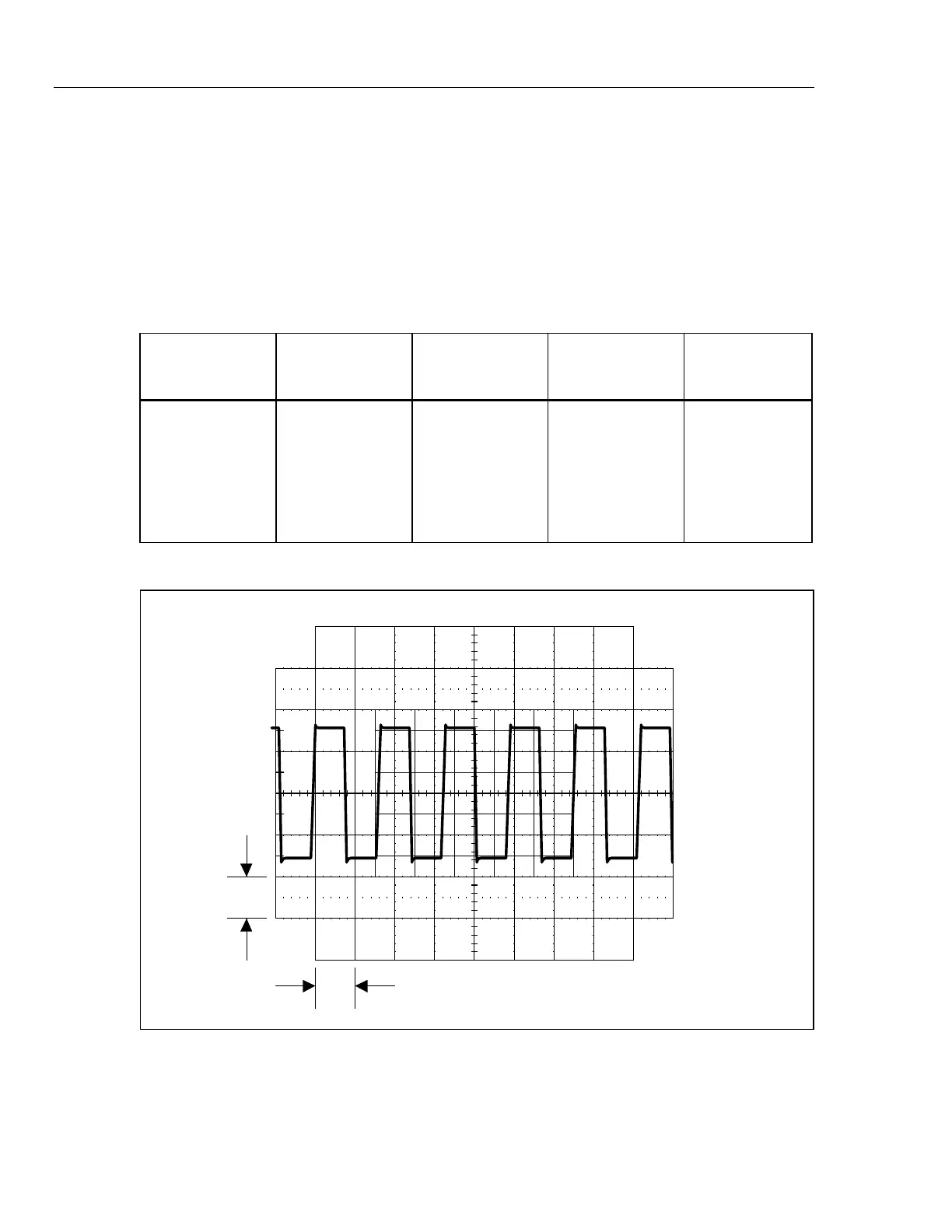
1 V
10 ms
F5-5.EPS
Figure 5-5. Waveform at Pin 6 of U9