Do you have a question about the Fluke 8060A and is the answer not in the manual?
| Display | 4.5 digit LCD |
|---|---|
| True RMS | Yes |
| Diode Test | Yes |
| Continuity Test | Yes |
| Operating Temperature | 0°C to 50°C |
| Power Supply | 9V battery |
| AC Voltage Range | 200 mV to 750 V |
| Frequency Range | 2 Hz to 200 kHz |
| DC Voltage Accuracy | ±(0.05% + 2 digits) |
| DC Current Accuracy | ±(0.2% of reading + 2 digits) |
| DC Current Range | 200 μA to 2 A |
| AC Current Range | 200 μA to 2 A |
| Weight | 650 g |
Overview of the 8060A multimeter's capabilities and features.
Lists the accessories included with the 8060A multimeter upon purchase.
Detailed electrical and environmental specifications for the 8060A multimeter.
Guide to using the 8060A multimeter and its measurement functions.
Instructions for checking the contents of the 8060A multimeter shipment.
Procedure for installing or replacing the 9V battery in the 8060A multimeter.
Details on how to check and replace fuses F1 and F2 in the 8060A multimeter.
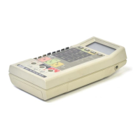
Description of the external physical characteristics of the 8060A multimeter.
Explanation of the controls, indicators, and connectors on the 8060A front panel.
Description of the 4 digit LCD display and its annunciators.
Maximum input voltage and current limits to prevent damage to the 8060A multimeter.
Overview of how to operate the 8060A multimeter's functions.
Describes the automatic self-test performed when the 8060A multimeter is powered on.
Procedure for selecting and performing AC/DC voltage measurements with the 8060A.
Explanation of the 8060A's True RMS measurement capability for AC signals.
How AC coupling affects AC voltage measurements on the 8060A.
Compares 8060A readings with average-responding meters for various waveforms.
Using the high impedance DC voltage function for sensitive circuitry.
Procedure for selecting and performing AC/DC current measurements with the 8060A.
Procedure for selecting and performing resistance measurements with the 8060A.
Explanation of the autoranging M resistance ranges on the 8060A.
Explanation of the autoranging k resistance ranges on the 8060A.
Procedure for performing conductance measurements and converting to resistance.
Procedure for testing diodes using the 8060A's diode test function.
How to use the Relative (REL) function to store and subtract reference values.
Procedure for performing frequency measurements with the 8060A.
Using the 8060A for dBm and dBW measurements, including reference impedance changes.
How to perform dBV measurements, commonly used in the audio industry.
Procedure for checking circuit continuity using the 8060A's audible and visible indicators.
Basic tests to verify the proper operation of the 8060A multimeter's functions.
Overview of various applications and measurement capabilities of the 8060A.
Procedure to determine amplifier bandwidth using dB, relative, and frequency functions.
Method to determine the Q factor of a tuned circuit using the 8060A.
Measuring amplifier stage gain referenced to an initial dB level using relative dB.
Applications of the 8060A in audio equipment testing and maintenance.
Method to measure very low currents using high impedance voltage function and resistors.
How to set different reference impedances for dBm/dBW measurements using the REL function.
Using a DC source to set reference impedances for AC voltage dB measurements.
Overview of the 8060A's operational principles and components.
Explanation of the major circuits (microcomputer, MAC) and signal flow.
Description of the 8060A's microcomputer role in control and operation.
Explanation of the MAC's function in signal acquisition and control.
Detailed breakdown of the analog-to-digital conversion process in the 8060A.
Theory behind the 8060A's voltage measurement input divider and protection.
Theory of operation for current measurements using shunts and the A/D converter.
Explanation of the ratio technique used for resistance measurements.
Theory of operation for conductance measurements, reversing the resistance technique.
Theory of how the 8060A detects and indicates continuity.
Theory of operation for frequency measurements using the MAC's frequency counter.
Introduction to the maintenance procedures for the 8060A multimeter.
Details on warranty, in-warranty, and out-of-warranty repair services.
Recommendations for periodic checks and performance tests.
Safety precautions for handling static-sensitive components within the 8060A.
General procedures for disassembling and reassembling the 8060A instrument.
Procedure to access calibration adjustments and the backup fuse (F2).
Steps to gain access to the main printed circuit board (PCB).
Procedures for disassembling and assembling the LCD and microcomputer PCB.
Instructions for replacing the backup fuse (F2) in the 8060A.
Guidelines for cleaning the exterior of the 8060A multimeter.
Procedures to verify the 8060A's performance against specifications.
Initial steps required before performing performance tests on the 8060A.
Testing the microcomputer and LCD display using the self-test feature.
Procedure to verify DC voltage, AC voltage, and dB functions using a calibrator.
Procedure to verify the proper operation of the resistance function.
Procedure to verify the continuity function's audible and visible indicators.
Procedure to verify the proper operation of the conductance function.
Procedures to verify the proper operation of DC and AC current functions.
Procedure to verify the proper operation of the diode test function.
Procedure to verify the proper operation of the frequency function.
Procedures for adjusting calibration to maintain specifications.
General guidance and precautions for troubleshooting the 8060A.
Description of the three self-test modes available on the 8060A.
Details on the ratio self-test mode for verifying the A/D converter.
How the switch decoding self-test verifies microcomputer interpretation of switch settings.
A guide to diagnosing and resolving common malfunctions based on symptoms.
Introduction to the list of replaceable parts for the 8060A multimeter.
Information on ordering replacement parts for the 8060A multimeter.
Information on manual revision levels and assembly documentation.
Notes on changes and improvements in newer instrument revisions.
Contact information for Fluke service centers worldwide.
Diagram showing component locations on the main PCB (A1).
Diagram illustrating the locations of various test points on the 8060A.
Graphical representation of the A/D measurement cycle stages.
Detailed view of the switches and their states in the 8060A.
Complete schematic diagram for the main PCB (A1) of the 8060A.
Complete schematic diagram for the A3 RMS PCB of the 8060A.


