Operation Instructions
Physical Features
2
2-7
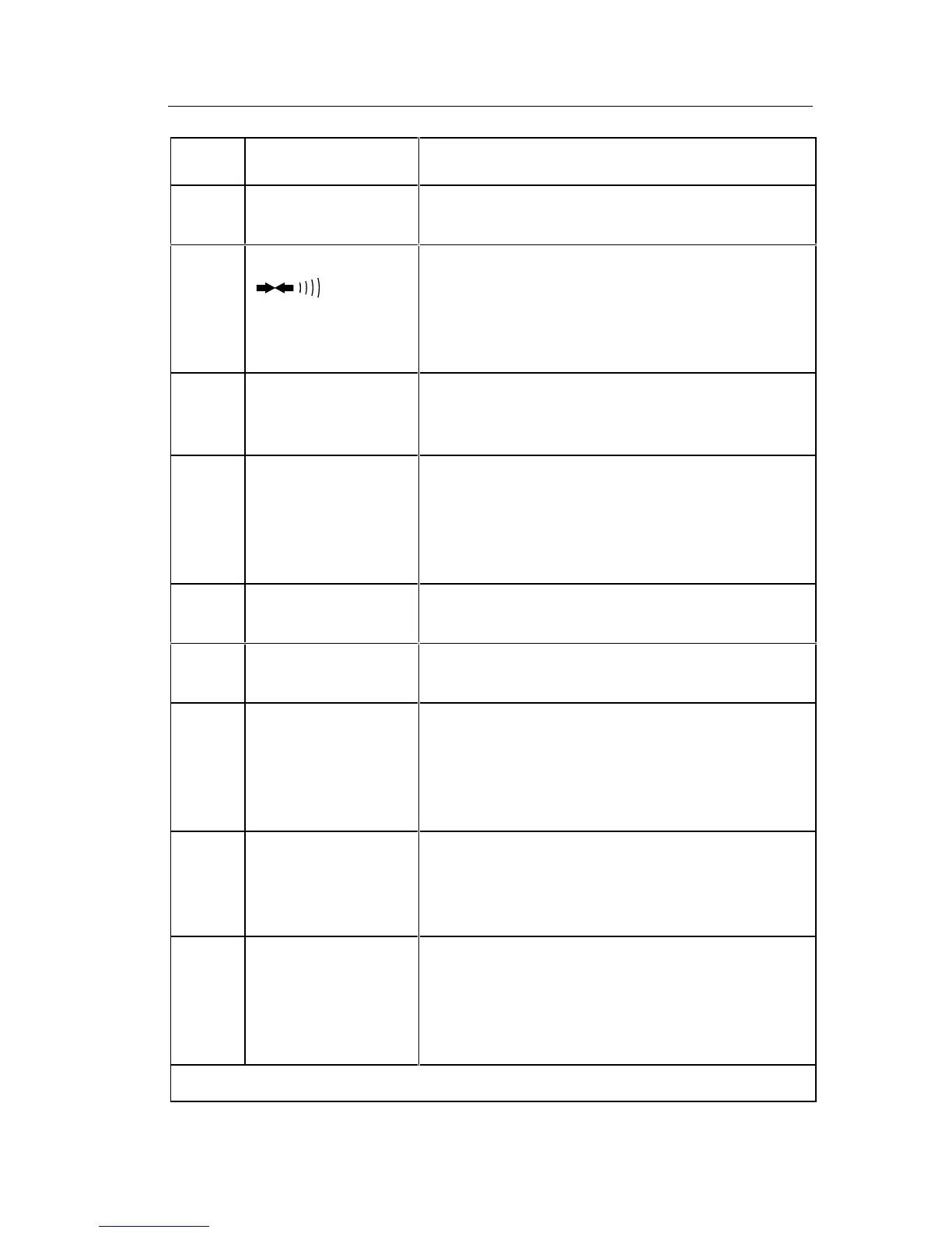
Table 2-1. Controls, Indicators and Connectors
Item
No.
Name Function
1W* Battery Eliminator
Connector
External input power connector for use with
the A81 Battery Eliminator accessory.
2 Function Buttons:
, REL
Push buttons that toggle on or toggle off the
‘secondary functions: visible or audible
continuity, or relative. These functions are
selected in conjunction with the primary
measurement functions (see items 7 and 8).
3 Battery
Compartment and
Cover
Cover for the 9V battery and the current fuse
F1.
4V Ω S Input
Connector
Protected test lead connector used as the
high input for all voltage, resistance, and
continuity measurements. All test lead
connectors accept standard or safety-
designed banana plugs.
5 COMMON Input
Connector
Protected test lead connector used as the
low or common input for all measurements.
6 A Input Connector Protected test lead connector used as the
high input for current measurements.
7 Function
Switches: A,V, Ω,
Interlocked switches that are used in
conduction with the input connectors to
select the measurement functions. Pushing
one switch releases the other, or both may
be pushed together.
8 AC/DC Function
Switch
Push-on/push-off switch is used to select ac
or dc for current or voltage measurements.
(Does not affect selection of diode test or
resistance functions).
9 Range Switches Interlocked switches that are used to select
ranges. Pushing a switch selects the
corresponding range and released other
switch depressions. Also used to select
conductance and the diode test.
* For safe operation, fully insert the A81.