Operation Instructions
Signal Input Limits
2
2-9
dy07f.eps
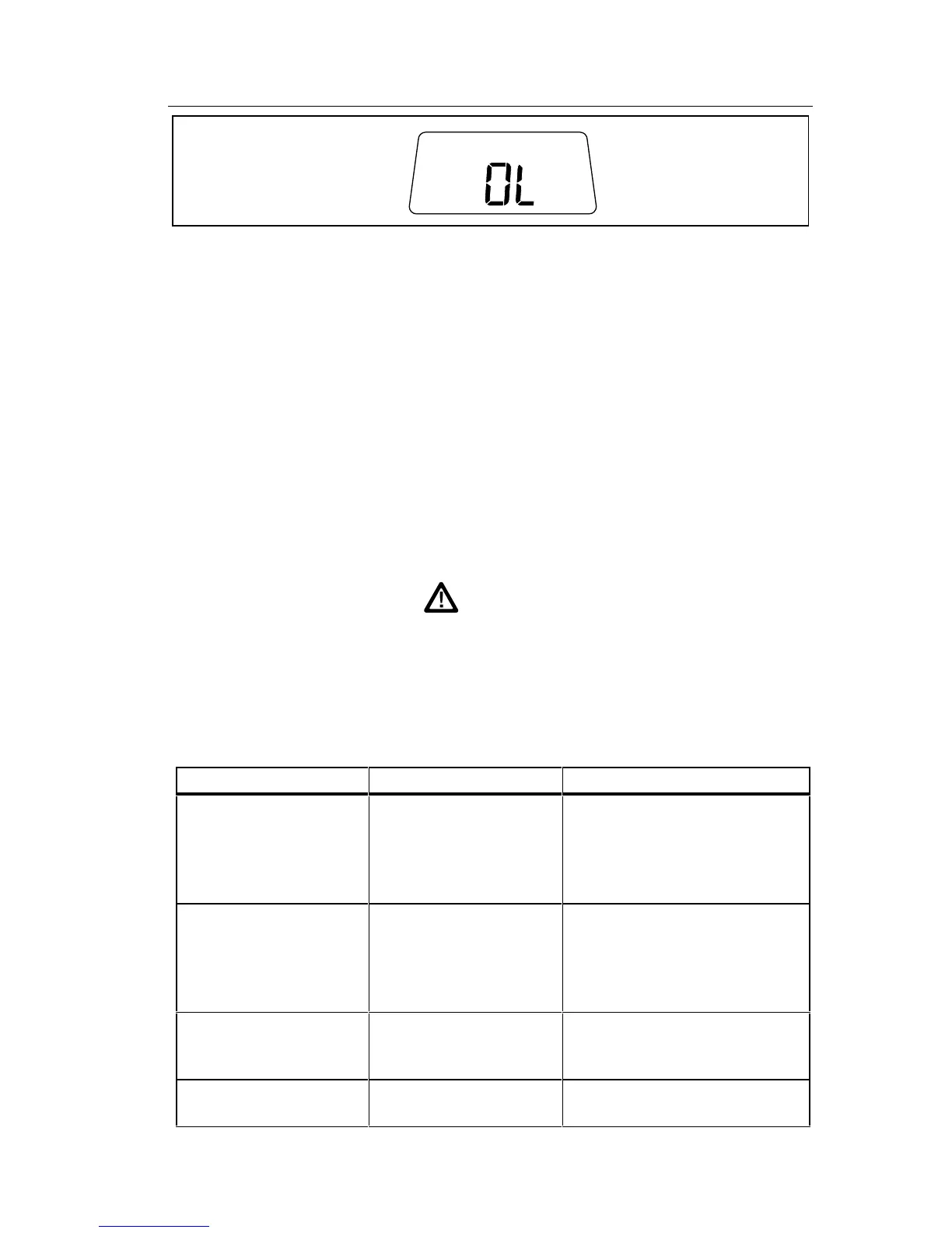
Figure 2-5. Overrange Indicator
2-8. Signal Input Limits
Caution
Exceeding the maximum input overload limits can
damage your instrument.
Before you begin to use your 8062A, it is important to note the maximum
inputs that may be applied to the instrument. Table 2-2 presents the
maximum inputs that are allowed for each function, range, and input
terminal.
Warning
To avoid electrical shock and/or instrument damage, do
not connect the common input terminal to any source
more than 500 volts dc or rms ac above earth ground.
Table 2-2. Input Overload Limits
Function Input Terminals Maximum Input Limit
AC Voltage VΩS and COMMON 750V rms or 1000V peak
continuous except 20
seconds maximum on the
200 mV range above 300V
dc or ac rms.
DC Voltage VΩS and COMMON 1000V dc or peak ac
continuous except 20
seconds maximum on the
200 mV and 2V ranges
above 300V dc or ac rms.
AC or DC Current A and COMMON 2A maximum, fuse
protected to 600V dc or ac
rms.
Resistance, Diode
Test, and Continuity
VΩ and COMMON 300V dc or ac rms.