8062A
Instruction Manual
4-16
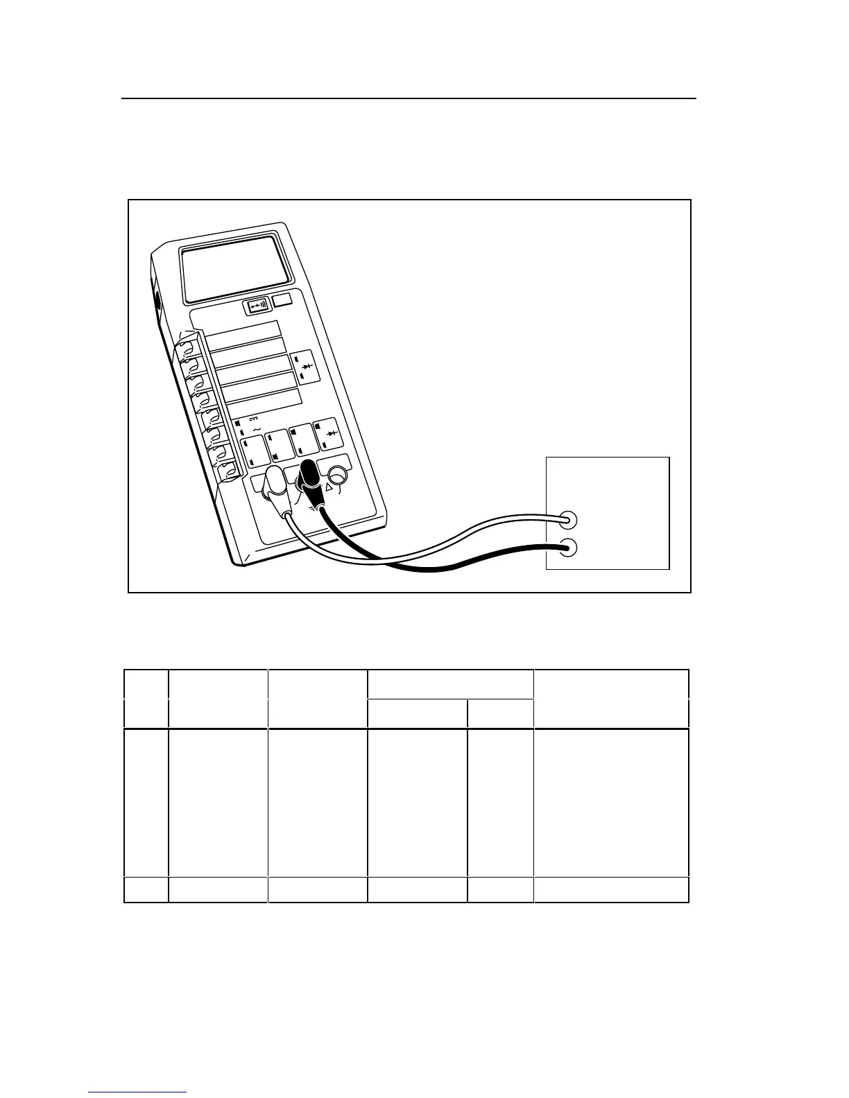
2. For each step in Table 4-4, select the UUT function and range as
indicated. Program the DMM Calibrator for the specified input signal
and verify that the displayed UUT value is within the indicated limits.
2000mA
A
A
COMMON
V Ω S
V
Ω
S
200mA
200
200k
200µA
DC
AC
200mV
200Ω
20mA
20
20k
2mA
2
2k
1000 DC
750 AC
MΩ
REL
1000V DC
750V AC
MAX
2A MAX
500V MAX
!
!
DMM
Calibrator
HI
UUT
LO
dy36f.eps
Figure 4-5. Equipment Connection for Current Test
Table 4-4. Current Test
Step Function Range Input Signal Display
Level Freq. Limits
1
2
3
4
5
6
7
Current dc
200 µA
200 µA
2 mA
20 mA
200 mA
2000 mA
2000 mA
190.00 µA
-190.00 µA
1.9000 mA
19.000 mA
190.00 mA
1900.0 mA
-1900.0 mA
dc
dc
dc
dc
dc
dc
dc
189.41 to 190.59
-189.41 to -190.59
1.8941 to 1.9059
18.941 to 19.059
188.65 to 191.35
1886.5 to 1913.5
-1886.5 to -1913.5
8 Current ac 20 mA rms 19.000 mA 1 kHz 18.848 to 19.152