Theory of Operation
Functional Description
3
3-9
The ac input voltages are divided with the same divider arrangement as the
dc input voltages, with the exception that the 2V ac voltage range is divided
by 10. The divider output signals for ac voltages are ac-coupled to the input
of a true rms ac converter which produces a current output. A negative dc
representation of the ac input signal is filtered and applied to the input of the
a/d converter.
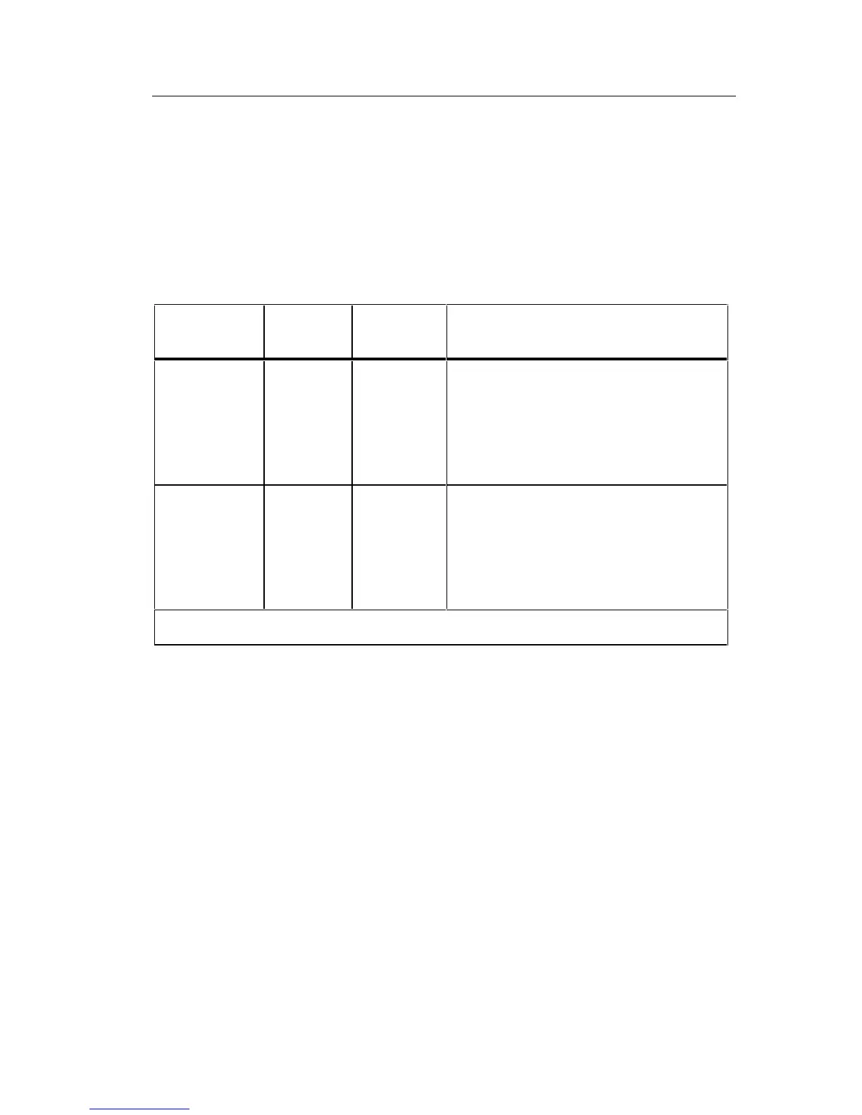
Table 3-1. Voltage Input Divider
Function Range
Input
Divider
Range of A/D Converter Input
DC Voltage
200 mV
2V*
20V
200V
1000V*
1/1
1/1
1/100
1/1000
1/1000
-200 mV to +200 mV
-2V to +2V
-200 mV to +200 mV
-200 mV to +200 mV
-2V to + 2V (1V max. input)
AC Voltage
200 mV
2V
20V
200V
750V*
1/1
1/10
1/100
1/1000
1/1000
0 to -200 mV
0 to -200 mV
0 to -200 mV
0 to -200 mV
0 to -2V (-0.75V max. input)
*Integrator gain in a/d converter reduced by factor of 10.
3-7. Current Measurement
Current measurements are made using a double-fuse-protected, switchable,
five-terminal current shunt (0.1 ohm, 1 ohm, 10 ohm, 100 ohm or 1 kilohm)
to perform the current-to-voltage conversion required by the a/d converter. A
block diagram of current measurements is shown in Figure 3-5. When the dc
current function is selected, the dc voltage drop across the shunt is filtered
and applied to the input of the a/d converter. When the ac current function is
selected the ac voltage drop across the shunt is ac-coupled to the input of the
true rms ac converter. The dc representation of the ac voltage is filtered and
applied to the input of the a/d converter. All current ranges use the
±
200 mV
a/d converter input range.